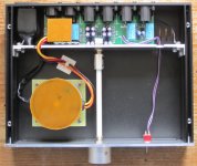
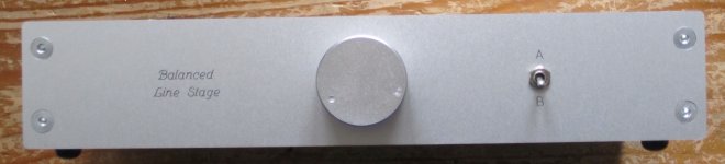
I built a couple of these in 230mm wide 1U Galaxy enclosures from modushop.biz aka HiFi2000.
Attachments
-
 1899d1460206730-bruno-putzeys-micropre-diyaudio_blog-1.jpg594.8 KB · Views: 538
 -
 1900d1460206730-bruno-putzeys-micropre-diyaudio_blog-2.jpg190.9 KB · Views: 526
 -
 1901d1460206730-bruno-putzeys-micropre-diyaudio_blog-3.jpg203.7 KB · Views: 506
 -
 1902d1460206730-bruno-putzeys-micropre-diyaudio_blog-7.jpg320.6 KB · Views: 530
Very nice build. I put mine in same enclosure, but not as good looking as yours. Back panel done by Frontpanel Express.
Jan
Jan
Very nice!I built a couple of these in 230mm wide 1U Galaxy enclosures from modushop.biz aka HiFi2000.
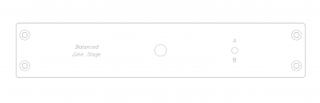
Do you still have the design files to cut the front + backplates?
Thank you! The design files for Front Panel Express are attached.
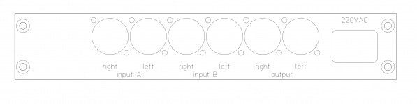
Note that the back panel is designed so that the volume knob can be in the center of the front panel while still using a 9mm pot the board is designed for. (The below doesn't apply for an off-board pot, relays, etc.)
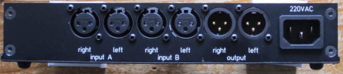
Vertically, knob in the center means that the board is placed relatively high in the enclosure. Because of that, the XLR connectors are closer to the top edge of the back panel than I would prefer. Also, such placement limits the height of the 4x 1000uF power supply capacitors (C12-C15) - some part numbers may be too tall.
Horizontally, it means the space for the AC power inlet is limited. I used Schurter 6100.4x30, which is a very compact snap-in inlet designed for a 3mm panel. One can drop the inlet and just use an old style permanently connected AC cord instead.
Finally, the inside support piece came out a bit ugly. Instead of four cutouts, I would rather have one hole in it opposite the AC inlet and another for the input selector switch wiring. Also, should the pot have any anti-rotation pin (as, for instance, Vishay Sfernice P9 has) or a different bushing, the center hole would need to be adjusted accordingly.
Note that the back panel is designed so that the volume knob can be in the center of the front panel while still using a 9mm pot the board is designed for. (The below doesn't apply for an off-board pot, relays, etc.)
Vertically, knob in the center means that the board is placed relatively high in the enclosure. Because of that, the XLR connectors are closer to the top edge of the back panel than I would prefer. Also, such placement limits the height of the 4x 1000uF power supply capacitors (C12-C15) - some part numbers may be too tall.
Horizontally, it means the space for the AC power inlet is limited. I used Schurter 6100.4x30, which is a very compact snap-in inlet designed for a 3mm panel. One can drop the inlet and just use an old style permanently connected AC cord instead.
Finally, the inside support piece came out a bit ugly. Instead of four cutouts, I would rather have one hole in it opposite the AC inlet and another for the input selector switch wiring. Also, should the pot have any anti-rotation pin (as, for instance, Vishay Sfernice P9 has) or a different bushing, the center hole would need to be adjusted accordingly.
Attachments
Last edited:
How are your caps cooking? They'll be toasty sat on the same plane as the regs. I folded my regs out forward for better thermal management.
The dissipation of the regulators depends on the transformer used - more specifically, on its secondary voltage. I used 2x12VAC and 2x15VAC in different builds, and I think I am ok thermally.
With higher voltage, I would increase R25-R28 a bit and/or add resistors in series with the transformer's secondary windings to drop some voltage and relieve the regulators.
On the other hand, Panasonic FC with d=10mm is rated for 3000 hours at 105°C, and more at a lower temperature, so maybe even a bit of overtemperature is ok.
Last edited:
Today i have finished the build...
I have a problem on the output.
whatever input/output combination, putting the oscilloscope between
pin 1 (GND) and 2
or
pin 1 and 3
of the output i get the signal only on the "hot" side (1-2)
(1-3) seems grounded.
After the input stage i have both signal correctly buffered and out of phase...
but then i get lost.
the only part substituted is the tl072, i have used a opa2277 that i had from another project. Anyway... no Dc offset on the output.
I have also simulated the circuit, and indeed the cold side is grounded.
I think i am missing an important bit of information here 😀
Can you guess what i can check next ?
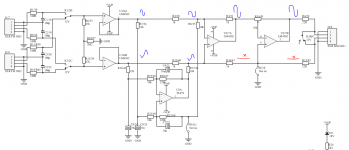
attached are the sim used
and how i see the signal on the circuit.
behavior is completely equal to right/left ... input1 or input2
I have a problem on the output.
whatever input/output combination, putting the oscilloscope between
pin 1 (GND) and 2
or
pin 1 and 3
of the output i get the signal only on the "hot" side (1-2)
(1-3) seems grounded.
After the input stage i have both signal correctly buffered and out of phase...
but then i get lost.
the only part substituted is the tl072, i have used a opa2277 that i had from another project. Anyway... no Dc offset on the output.
I have also simulated the circuit, and indeed the cold side is grounded.
I think i am missing an important bit of information here 😀
Can you guess what i can check next ?
attached are the sim used
and how i see the signal on the circuit.
behavior is completely equal to right/left ... input1 or input2
Attachments
Last edited:
Today i have finished the build...
I have a problem on the output.
whatever input/output combination, putting the oscilloscope between
pin 1 (GND) and 2
or
pin 1 and 3
of the output i get the signal only on the "hot" side (1-2)
(1-3) seems grounded.
After the input stage i have both signal correctly buffered and out of phase...
but then i get lost.
the only part substituted is the tl072, i have used a opa2277 that i had from another project. Anyway... no Dc offset on the output.
I have also simulated the circuit, and indeed the cold side is grounded.
I think i am missing an important bit of information here 😀
Can you guess what i can check next ?
attached are the sim used
and how i see the signal on the circuit.
behavior is completely equal to right/left ... input1 or input2
Sorry...
I have completely overlooked the circuit topology here. 😉
i was expecting the output to reflect the input signals. Hot "in-phase" and a Cold "out-of-phase" couple.
Instead this circuit is an impedance balanced sender... totally different beast.
that circuit can't work for the amp i am using...
in the end... lesson learned... look and read more carefully.
Why can’t this circuit work for your amp ?Sorry...
I have completely overlooked the circuit topology here. 😉
i was expecting the output to reflect the input signals. Hot "in-phase" and a Cold "out-of-phase" couple.
Instead this circuit is an impedance balanced sender... totally different beast.
that circuit can't work for the amp i am using...
in the end... lesson learned... look and read more carefully.
It’s a true balanced output. On the receiver side nobody notices whether pin2 and pin3 are differential or not, only the voltage difference between the two pins count.
Hans
Why can’t this circuit work for your amp ?
It’s a true balanced output. On the receiver side nobody notices whether pin2 and pin3 are differential or not, only the voltage difference between the two pins count.
Hans
Aside from the fact that this amp expects two signal out of phase as input.
is not a true differential input.
rather a dual single-ended.
Aside from the fact that this amp expects two signal out of phase as input.
is not a true differential input.
rather a dual single-ended.
No amp with a balanced input expects two signals out of phase.
As already mentioned, the only thing a balanced input expects is a voltage difference between pin2 and pin3, plus that both phases are having the same output resistance at the source.
Hans
No amp with a balanced input expects two signals out of phase.
As already mentioned, the only thing a balanced input expects is a voltage difference between pin2 and pin3, plus that both phases are having the same output resistance at the source.
Hans
... think that as bridge amp
it needs two signal that are out of phase.
Mine doesn't take care of the differential signal treatment. rely on an external source for providing that.
Last edited:
... think that as bridge amp
it needs two signal that are out of phase.
Mine doesn't take care of the differential signal treatment. rely on an external source for providing that.
O.k. I give up.
You know better.
Hans
I am not saying i know more...
The amp has an XLR input
and expect two signal out of phase.
it hasn't a balanced nor a differential input.
😀
The amp has an XLR input
and expect two signal out of phase.
it hasn't a balanced nor a differential input.
😀
Today i have finished the build...
I have a problem on the output.
whatever input/output combination, putting the oscilloscope between
pin 1 (GND) and 2
or
pin 1 and 3
of the output i get the signal only on the "hot" side (1-2)
(1-3) seems grounded.
After the input stage i have both signal correctly buffered and out of phase...
but then i get lost.
the only part substituted is the tl072, i have used a opa2277 that i had from another project. Anyway... no Dc offset on the output.
I have also simulated the circuit, and indeed the cold side is grounded.
I think i am missing an important bit of information here 😀
Can you guess what i can check next ?
attached are the sim used
and how i see the signal on the circuit.
behavior is completely equal to right/left ... input1 or input2
You see that net tie at J4?
Jan
I am not saying i know more...
The amp has an XLR input
and expect two signal out of phase.
it hasn't a balanced nor a differential input.
😀
Balanced refers to the impedance from each line being the same. Balanced does not say anything about the signal levels on each line to ground; as soon as you start measuring to ground, you violate the idea of differential signals which are supposed to be undefined to ground.
So as long as the two lines have similar impedances, it's balanced, and it is differential if the signal is defined as the difference between the two lines.
You really should read Bruno's article, to avoid all this confusion. This project was just a free goody to illustrate the principles he explained in the article.
Jan
I swapped out the attenuator for a tkd 2cp-601. I now have much better channel matching. Its within 1% across the full range. Most of the volume comes in the first quarter turn but that suits the level I listen at as my power amps are only 20db gain.
Worth trying if you find the channel balance a little skewed.
Worth trying if you find the channel balance a little skewed.
- Home
- Source & Line
- Analog Line Level
- BPPBP - Bruno Putzey's Purist Balanced Preamp (well a balanced volume control really)