BPPBP - Bruno Putzey's Purist Balanced Preamp (well a balanced volume control...
Not sure about that, the source signal return is connected to pin 3 at the receiver. The chassis is connected to pin 1. Sure, they then meet at the source. My understanding I think was that the cable's impedance and/or the preamp's input buffer acted as in Jensen's description. Will give it a thorough read, thanks for pointing me to the document.
Yoy're saying Bruno's suggestion is wrong...?That wiring of the screen does not work.
You have connected the Source Signal Return to the Chassis of the Receiver.
Not sure about that, the source signal return is connected to pin 3 at the receiver. The chassis is connected to pin 1. Sure, they then meet at the source. My understanding I think was that the cable's impedance and/or the preamp's input buffer acted as in Jensen's description. Will give it a thorough read, thanks for pointing me to the document.
Last edited:
I am saying that your diagram is wrong.
You have connected the Source Signal Return to the Receiver Chassis.
You have connected the Source Signal Return to the Receiver Chassis.
BPPBP - Bruno Putzey's Purist Balanced Preamp (well a balanced volume control...
It's not my diagram, it's taken from the Ncore manual in the link as stated.
And I still don't see the point, the source signal return us directly connected to pin 3, while the receiver chassis is connected to pin 1?
It's not my diagram, it's taken from the Ncore manual in the link as stated.
And I still don't see the point, the source signal return us directly connected to pin 3, while the receiver chassis is connected to pin 1?
...of course if you use a rotary encoder you can use the uC to select inputs and display them....heheh
It's interesting to see how fast you converge to my solution once you start thinking it through. Normally it takes a few days 😉😀
Jan
That's sad Bill. The production company in fact has quite high initial setup cost (160€, plus 240€ for the stencil [is that the proper English term?] and 90€ for programming), well I'm already taking quite a substantial part of that on me. Since they shall do the production of the modules mini series, I'd wanted to keep that in one hand.
The PCBs are FR4 material, 1.5mm, double sided with solder resist, mounting print one sided, nickel/gold min. 0,05μ Au to IPC Class 2, visual and electric testing.
If we manage to get to 50 PCBs, the price will go down to 17.25€ .
Well it's your group buy but your PCB manu is charging outrageous prices. My not-so-cheap eurocircuits want € 115 for 10, € 160 for 20 or € 190 for 30. Or € 250 for 50 - that's € 5 a piece. 7 working days.
No setup, no design, no nothing.
Ex VAT so depending on your situation you may need to add a buck. Still very good.
Maybe offer either blank boards or the whole shebang.
Jan
Last edited:
your posted diagram shows pin 1 connected to chassis. that is correct.It's not my diagram, it's taken from the Ncore manual in the link as stated.
And I still don't see the point, the source signal return us directly connected to pin 3, while the receiver chassis is connected to pin 1?
Pin 1 is also connected to screen/shield. That screen is connected to source RCA Signal Return.
That connects Receiver chassis to Source signal.
That is wrong.
Edit.
I have quickly read the notes attached to page13 diagram.
I don't like it, partly because I have never built a ClassII preamp with the Source Chassis Safety grounded to the Receiver via the RCA sockets.
It might work if you follow exactly what B.Putzeys states in the notes.
A 3pole socket at the source completely overcomes all and any reservations I have on using a ClassII or ClassI preamp.
Last edited:
Well it's your group buy but your PCB manu is charging outrageous prices. My not-so-cheap eurocircuits want € 115 for 10, € 160 for 20 or € 190 for 30. Or € 250 for 50 - that's € 5 a piece. 7 working days.
No setup, no design, no nothing.
Ex VAT so depending on your situation you may need to add a buck. Still very good.
Thank you Jan for this information!
Do eurocircuits produce to the same standards as quoted above? (PCBs are FR4 material, 1.5mm, double sided with solder resist, mounting print one sided, nickel/gold min. 0,05μ Au to IPC Class 2, visual and electric testing)
I don't have the Gerbers etc. here today but will definitely investigate tomorrow when I'm back. If the production quality is comparable I'll definitely chose this cheaper option and adjust Group Buy prices accordingly.
Thanks,
Robert
Bertel,That wiring of the screen does not work...............
Look at Jensen's ap note 003, page3 section 2.4............
look at section 2.1
It shows B.Putzeys signal return connected to Source Chassis.
Read the notes about how badly this performs compared to the later alternatives. Better, best, a simple alternative.
Last edited:
Thanks Andrew. I will read and try to understand why Bruno and Jensen recommend differently here.
Do it CeeVee, quick, and let us know! 🙂
To do it quick you could always buy a muse module with display and input switching from Akouo and you are up and running.
I also have a few kits i got direct from japan which have just the volume control...really tiny.
It is definitly on my list to complete soon 🙂
Last edited:
It's interesting to see how fast you converge to my solution once you start thinking it through. Normally it takes a few days 😉😀
Jan
...well it is a very attractive solution.
The UGS Muse version Control board fits your requirements and mine ...to the T.
Open source code, bin file available , lovely display choices and input selection just right...4 i believe ( might be wrong ) ...we don't really need 6,8....umpteen inputs, and gerbers will be available as well.
Perfect for many preamps including this one.
Thank you Jan for this information!
Do eurocircuits produce to the same standards as quoted above? (PCBs are FR4 material, 1.5mm, double sided with solder resist, mounting print one sided, nickel/gold min. 0,05μ Au to IPC Class 2, visual and electric testing)
I don't have the Gerbers etc. here today but will definitely investigate tomorrow when I'm back. If the production quality is comparable I'll definitely chose this cheaper option and adjust Group Buy prices accordingly.
Thanks,
Robert
Eurocircuits are the people that produced the giveaway boards for the Linear Audio article.
If you are interested I can send you the files to upload for an order. They have an extensive on-line checking app so you see exactly how it will look.
Jan
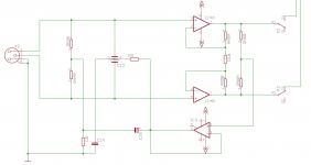
Motivated by this thread I resumed working on my own version of a Putzeys inspired balanced Preamp.
The input-boards are almost ready, including XLR connectors, the Whitlock bootstrapping circuitry, low noise voltage regulators and two relays + some logic to control them.
One board represents one stereo-channel, so this is not a cheap solution. But I need only two channels and so I'm most flexible for possible expansion.
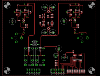
The schematic shows one channel, the full top layer is on the other picture.
The connectors are on the others side of the board.
Now I start working on the "main board" with the instrumentation amp and the volume control. But I'm still insecure for what kind of volume control to use...
The input-boards are almost ready, including XLR connectors, the Whitlock bootstrapping circuitry, low noise voltage regulators and two relays + some logic to control them.
One board represents one stereo-channel, so this is not a cheap solution. But I need only two channels and so I'm most flexible for possible expansion.
The schematic shows one channel, the full top layer is on the other picture.
The connectors are on the others side of the board.
Now I start working on the "main board" with the instrumentation amp and the volume control. But I'm still insecure for what kind of volume control to use...
Attachments
Pin1 goes to Chassis.
Do not connect Pin1 to audio ground.
The two ends of the shield connect to Pin1 and these connect to the chassis at each end.
This creates in affect ONE chassis with a "tunnel" between the two big halves.
Where the shield connects to pin1 in the plug and where pin1 connects to the chassis, do not use long pigtails.
If you must use a pigtail it MUST be very SHORT.
Better to use a wide, thin and short strap for this low impedance connection.
Pin1 goes to Chassis.
Do not connect Pin1 to audio ground.
The two ends of the shield connect to Pin1 and these connect to the chassis at each end.
This creates in affect ONE chassis with a "tunnel" between the two big halves.
Where the shield connects to pin1 in the plug and where pin1 connects to the chassis, do not use long pigtails.
If you must use a pigtail it MUST be very SHORT.
Better to use a wide, thin and short strap for this low impedance connection.
What you say is correct- first I wanted to put a jumper and a solderpad close to this Pin, so that I can decide whether Pin 1 goes directly to chassis or to ground.
But meanwhile I have removed the connectors from the board to use chassis mount connectors.
This has a lot of other advantages...
Apart from that- the "differential circuit" should be inherently immune to Pin 1-problems.
the signal comes in on pins 2 and 3.
Pin1 is only there to help with attenuating interference.
Interference on Pin1 must NOT be coupled to the audio.
Pin1 is only there to help with attenuating interference.
Interference on Pin1 must NOT be coupled to the audio.
Motivated by this thread I resumed working on my own version of a Putzeys inspired balanced Preamp.
The input-boards are almost ready, including XLR connectors, the Whitlock bootstrapping circuitry, low noise voltage regulators and two relays + some logic to control them.
One board represents one stereo-channel, so this is not a cheap solution. But I need only two channels and so I'm most flexible for possible expansion.
The schematic shows one channel, the full top layer is on the other picture.
The connectors are on the others side of the board.
Now I start working on the "main board" with the instrumentation amp and the volume control. But I'm still insecure for what kind of volume control to use...
Curious, what's going on with C13 and R9 ?
.
Curious, what's going on with C13 and R9 ?
.
C13 and R9 were parts of the bootstrapping circuit invented by Bill Whitlock:
The common mode signal is buffered by IC 3 and fed via R9 to the capacitor C13.
C13 is actually an X2Y cap, which is a bit like a capacitor with a center tap. This provides better symmetry than two single caps.
This circuit achieves a very high common mode input impedance.
Instead of C13 you will normally see two caps in series between the + and - input with their center connected to ground. This causes the common mode impedance to decrease with frequency.
Thanks. I also notice that you are doing something with the component layout, where it looks like the trace from R9 runs underneath C13.
Cheers !
- Home
- Source & Line
- Analog Line Level
- BPPBP - Bruno Putzey's Purist Balanced Preamp (well a balanced volume control really)