Hi guys, the output capacitor C103 =10uF can be changed by 22uF? Will the output frequency response changes alot?
Hello likeDIY,
That will depend on the impedance which loads your BOZ.
You can calculate it out with:
Fc=1/2*pi*R*C.
where Fc= your freq response
R=the load impedance for your BOZ
C=10 or 22uF.
Best Regards:
Nexus
🙂
That will depend on the impedance which loads your BOZ.
You can calculate it out with:
Fc=1/2*pi*R*C.
where Fc= your freq response
R=the load impedance for your BOZ
C=10 or 22uF.
Best Regards:
Nexus
🙂
Ok, I will give it a go with a 22uF.
The values of resistors must exactly the same as in the circuit? I'm abit lazy not to make the 33.2K and 22.1k, or 4.75K, in stead I just make it 33k, 22k, 4.7 respectively. Would it be much difference?
The values of resistors must exactly the same as in the circuit? I'm abit lazy not to make the 33.2K and 22.1k, or 4.75K, in stead I just make it 33k, 22k, 4.7 respectively. Would it be much difference?
Help help help.
It's blown up !!!!!
After connecting to the AC source, it's blown up :-(
The two resitors R2 and R3 are the first to get fire...
Please help, what is the problem? I'm quite sure that I connect the polar of the components correctly.
It's blown up !!!!!
After connecting to the AC source, it's blown up :-(
The two resitors R2 and R3 are the first to get fire...
Please help, what is the problem? I'm quite sure that I connect the polar of the components correctly.
Your amp is drawing a lot of current! What sets the current is the voltage at the mosfet's Source and the source resistor; are R101, P102, and R108 correct value and placement? Or maybe you have a short circuit (to gnd) somewhere? Did you smoke any other components?
I think I should check the P102, how can we indicate the CW and CCW for the P102 as shown in the circuit?
As soon as it gets smoke, I disconnect the power, so hopefully no other things get burn.
As soon as it gets smoke, I disconnect the power, so hopefully no other things get burn.
One more point, before making the PCB, I have mirrored the image and print it out, It might be a problem with the pin connection?
One more point, before making the PCB, I have mirrored the image and print it out, It might be a problem with the pin connection?
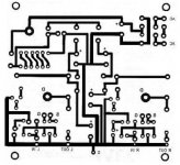
Ready made PCB is available here.
 Compromised URL removed by Moderation
Last edited by a moderator:
That should be correct. Are you shure there are no shorts? After you are shure there are no errors, try it with only one channel at a time 😉
I didnt notice whether it's the TIP41C or just TIP41 :-(
I asked the seller and he said TIP41 is better than TIP29.
I'm at work so couldnt verify now.
I asked the seller and he said TIP41 is better than TIP29.
I'm at work so couldnt verify now.
Hello,
I prepared my BOZ on testboard. It works fine with SEWA. I really like the sound of this duo. Mads, can we expect your BOZ pcb in near future?
Regards,
Zoltan
I prepared my BOZ on testboard. It works fine with SEWA. I really like the sound of this duo. Mads, can we expect your BOZ pcb in near future?
Regards,
Zoltan
- Status
- Not open for further replies.
- Home
- Amplifiers
- Pass Labs
- BOZ preamp project