This does help a lot, I can pretty much figure the 6sn7 pins out because I could see the examples. But I don't recall seeing the 100 attached to pin 3 of the b300. I feel really out of my league here.100r at pin 3 of 300B on Skunkie Designs schematic, not on original schematic
it's best to go one by one, then check the box that you have finished so you know where it has been done.
View attachment 1256139
I didn't watch all the videos so I don't really know but it does show on the mod schematic. It's best you focus on the schematic instead of watching videos. As long as you understand the schematic you can do anything.
For example how to install the 100r resistor on pin 3. Either cut the trace or remove the solder from 300B pin 3 then solder the 100r resistor.


For example how to install the 100r resistor on pin 3. Either cut the trace or remove the solder from 300B pin 3 then solder the 100r resistor.
If it's to the g on the board I have one there, took little pin out. I couldn't get your list to print completely, only the top of the page
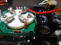
I put a 2w 100 ohm there! I ordered some new part's and I WILL have a safety pin to clean the holes out. A sewing needle didn't work well!
Looking at your diagram I see what I did is way different than what you have there! I didn't see that at all. I saw a video that showed what I did. Like you said reading the schematic is the key, except that I don't really know how!
More of a monkey see monkey do, or tries!
More of a monkey see monkey do, or tries!
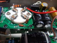
You're playing with high voltage and you didn't post the picture with the 100r mod that you did so it's hard to tell.
BTW, stephe's version show 110v version. However, I saw there are 110, 115, 120 versions out there. If your is 120v, it may not necessary to mod the power supply section.
If your version is exactly as stephe's videos, then you can follow as it. Otherwise, use the schematic is the best.
If you don't cut the trace or remove the little pin there, the 100r wouldn't do anything even you put in the right place.
Hope the traces below are helping.

That helps a lot, another question. Does the brown wire next to the 33uf go the pins that are jumpers on the 6sn7?
Honestly, I don't have one of these here and it's been a long time since I worked on this. Do you have the schematic?
I did both sides exactly the same way so channel 1 left side w amp upside down is not as neat because it looks backwards and brown wire won't reach pin 5 as is.
Last edited:
- Home
- Amplifiers
- Tubes / Valves
- Boyuurange A50 300B Review + Mods Series