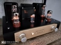
The first rule of upgrading / making improvements . . .
Get it working 100%. Then make changes.
Working 100% means that you can explain the different voltages and currents, etc. with the amp wired per the original circuit.
Swapping tubes of the same type (literally the same type, not just an "equivalent" type), can cause slightly different voltages, currents, and self bias voltage, but not large differences.
Changing from a rectifier tube that has a significant DCV drop, to all solid state rectification will make the transformer to
run much hotter, especially if you use the same B+ filter capacitances, chokes, and resistors.
All of my amplifiers that use old power transformers that used to run vacuum tube rectifiers . . .
I have compensated for that by:
Either using a first filter cap that has Much lower capacitance than the original cap.
Or I use a Choke input filter.
And . . .
I sometimes run the B+ at lower current levels than the original amplifier.
I do the same for the filament windings, example a 3.6A 6.3V filament secondary that now is only required to run 3.3A, or even only
1.9A. Also, the 5V filament secondary is not even used.
The old transformers run cooler than they did in the original amplifier.
I look at an old chassis and power transformer just like a stonecutter looks at a diamond. "He says, how will I cut this stone to best advantage?".
I look at the chassis and power transformer and ask: "what kind of an amplifier can I build with this".
I like to run transformers, tubes, and other parts at quite conservative levels.
A physically larger resistor with the same resistance and current, will get rid of heat quickly, because of the larger surface area. The parts that are next to the resistor will not be overcome with the higher temperature of a physically smaller resistor. Dissipation is the same, the temperature is not.
There are many many holes in the bottom plate. And there are some holes in the top of the chassis. Cool!
My amplifiers can run in the summer and not drive you out of the corner of a room.
And everything will run for a very very long time.
I am not a power freak. I am a finesse freak.
Last edited:
"Changing from a rectifier tube that has a significant DCV drop, to all solid state rectification will make the transformer to
run much hotter, especially if you use the same B+ filter capacitances, chokes, and resistors."
Surely you mean they run cooler with solid state rectification?
Am I to understand that simply increasing the rail voltage increases the overall power available?
Does this affect biasing, either fixed or cathode-based?
I suspect not but want to hear from the pros.
Last edited:
Those are good transformers, but that's overkill.
Each of them costs (and probably weights) more then the whole A9 amp.
And they're huge - will they even fit on the chassis?
Each of them costs (and probably weights) more then the whole A9 amp.
And they're huge - will they even fit on the chassis?
Well, it depends.Surely you mean they run cooler with solid state rectification?
The current through the PT is roughly the sum of the current consumed by the amp itself and the current pulses that are charging the reservoir caps. Since the SS rectifier has lower impedance, those current pulses will be bigger.
You'll probably get about 20-25% current increase just by changing 5Z3 to UF4007. You can drop it to 10-15% by replacing the 22uF first cap with the 10uF one, still gaining a good bit of B+ voltage.
On the other hand, you save 12-15W that were heating the 5Z3, and you don't heat the PT with the rectifier tube itself (not that it matters much, since it is heating mostly the core and not the copper, but still).
It does. You'll have to increase cathode resistors to get to the same quiescent current as before.Does this affect biasing, either fixed or cathode-based?
I suspect not but want to hear from the pros.
Tubby23,
1. Capacitor input B+ filter:
The transient current in a B+ supply is primarily due to these factors:
The current draw of the load
The DCR of the primary x the ratio of primary/secondary
The DCR of the 1/2 winding of the secondary (when using the center tap, and full wave rectification, just like you are using)
The Voltage of the 1/2 secondary
With a Cap input B+ filter, the capacitance of the 1st cap
The Dynamic resistance and voltage drop of the rectifier (much larger for a tube rectifier, much lower for solid state rectifiers).
For a cap input B+ filter, the transient currents of the first cap are very large (much larger than the load current is).
The heating of the primary DCR and the secondary DCR are according to
(I squared) x (DCR in series with the rest of the resistances).
Understand, that is current x current x DCR (and all the other resistances leading up to the first capacitor. That includes the tube rectifier with its medium resistance (normally as much or more than the DCR of the windings).
A solid state rectifier has almost no resistance (more transient current if everything else remains the same).
Cap input B+ . . .
current squared x (all the resistances and DCRs and effective DCRs in series)
The [Heating] integral of all this is Large.
The peak voltage to the rectifier is 1.414 x the 1/2 winding rms voltage of the secondary.
The advantage of a cap input B+ filter is that the 1/2 secondary voltage is lower to get a specific B+ voltage, and that means less secondary turns, saves money, saves weight,
and is wonderful for manufacturers that want to cut manufacturing and shipping costs.
Every penny counts. And, there are less capacitors and resistors to get the B+ hum filtering to a specified low level.
2. Inductor input B+ filter:
On the other side of circuit design, is the B+ that uses choke input filter (the first cap is After the choke).
The current is no longer a large transient, instead, it is an Average current.
The integral of (I squared) x R Heating losses are much smaller than with the cap input supply.
If you look at the 2 curve charts for a vacuum tube rectifier, you will find that the Choke input curves can take much more rectifier load current, and can take much higher rectifier plate voltage.
That is because choke input supplies are "easier" on tube rectifiers. And if it is easier on the tube, it is also easier on the power transformer.
The disadvantages are:
The peak voltage that is rectified is 0.9 x the 1/2 winding rms.
That sounds like the Average. 2/pi = 0.637. (the average of a full wave rectified sine wave).
1.414 x 0.637 = 0.9
That require more secondary turns, more wire, more weight, more cost.
And, in order to get the same filtering action, usually one extra capacitor and one extra resistor are required too after what would have been the last cap in a cap input filter (more weight, space, and cost).
3. Practical implementation:
I use pre-owned transformers that were originally running vacuum tube rectifiers.
I use solid state rectifiers, and whenever possible I use Choke input filtering.
Those transformers run cooler than they did in their original amplifiers.
I use completely different amplifier circuits and parts than the original amplifiers (only the original power transformer and original chassis are used).
Even though they are very old, the old power transformers will run for a very long time (I use them in the summertime too).
Cool!
3. A.
But, you are trying to increase the output power of you amplifier using the power transformer that you have.
You will not be able to use choke input filtering. Even with solid state rectifiers instead of a tube rectifier, you will get Less B+ voltage.
Generalizations:
Given a minimum load, and at least critical inductance, a choke input B+ has much better voltage regulation than a capacitor input B+.
Cheap is Not Good
Good is Not Cheap
Last edited:
I'm not actually sure that upgrading the OPTs is very useful given that PT doesn't allow to bias the tubes hotter. You'll get maybe extra 5% power, and that's about it.
So I would either leave the amp as it is or upgrade the PT first.
Another thing you can do is switching to SS rectification to boost the B+ voltage (you'll probably have to replace the electrolytic caps too though).
Hey there,
One thing I'm going to try is replacing the 5Z3P/5U4G rectifier tube with a 5ar4/gz34.
This has a voltage drop of just 10v vs the 40v of the 5Z3P.
Also, it's heater current is only 1.9A vs the 3A of the 5Z3P.
That'll bump up my rail and voltages by about 30v in addition to the 1A power saving.
I'm expecting substantially less sag so I may try increasing the bias once more without fear of losing bass again.
Actually, I may not have to... With the higher voltages bias will increase on its own, I believe. I'm hoping for it to settle somewhere between 70-80% of max plate dissipation.
After replacing the 5Z3P for the 5AR4/GZ34 all my voltages have gone up by about 20v and there's less 1A of heater drawer on the PT.
Providing your caps aren't right on the edge, and you haven't messed with biasing yet, it's a straight swap.
Compared to the coke bottle 5Z3P this tube is tiny - about the same size as the input tubes.
Thing to note is it takes quite a bit of extra time to warm up - about 25 seconds or so before HT appears on the rails so be patient on its first run, don't freak out and think it's malfunctioning.
Sound wise, I'm finding the bass a bit more punchy although I'm hearing that same harshness I heard when I first turned on the amp, so this rectifier needs a little breaking in.
But, I highly recommend this inexpensive and straight swap.
IMHO, it's much easier on the A9 then going fullout SS.
Attachments
The 5Z3P filament is 5V @ 3 Amps.
Its filament is quite massive.
The 5AR4 filament is 5V @ 1.9 Amps.
I bet the power transformer is providing less than 5V to the 5Z3P.
That and the more massive filament would explain the slower warm up time.
Its filament is quite massive.
The 5AR4 filament is 5V @ 1.9 Amps.
I bet the power transformer is providing less than 5V to the 5Z3P.
That and the more massive filament would explain the slower warm up time.
The 5Z3P filament is 5V @ 3 Amps.
Its filament is quite massive.
The 5AR4 filament is 5V @ 1.9 Amps.
I bet the power transformer is providing less than 5V to the 5Z3P.
That and the more massive filament would explain the slower warm up time.
The OEM tube is the 5Z3P with its 5v/3A heater.
I swapped that out for the 5AR4 with its indirectly heated 5v/1.9A heater.
The newly installed 5AR4 is what's giving me more voltage on my rails and less current draw from its heater.
I see that as a win/win, despite the longer warm-up time (of 5AR4) which adds to the charm.
Last edited:
Rectifiers 5V
Here is a list of tubes with direct or indirect heating
Here is a list of tubes with direct or indirect heating
Attachments
Last edited:
Here is a list of tubes with direct or indirect heating
Nice one!
Real Tubes:
The JJ 5Y3S is a Directly Heated rectifier.
This is modern quality production, just like the original ones in the 40s and 50s.
Filaments only, no Cathode.
Bogus tubes !
The Sovtek 5Y3GT is Indirectly Heated.
It is similar to the 5AR4 in construction, it has a real Cathode.
Just Sayin'
The JJ 5Y3S is a Directly Heated rectifier.
This is modern quality production, just like the original ones in the 40s and 50s.
Filaments only, no Cathode.
Bogus tubes !
The Sovtek 5Y3GT is Indirectly Heated.
It is similar to the 5AR4 in construction, it has a real Cathode.
Just Sayin'
Is there a limit on how many watts an output transformer for a single ended, single tube amp can have?
I keep hearing how these amps are often referred to as "fly watts" , little, etc. Is it only because PP transformers are smaller and cheaper?
What's the biggest opt a single el34 can drive?
I keep hearing how these amps are often referred to as "fly watts" , little, etc. Is it only because PP transformers are smaller and cheaper?
What's the biggest opt a single el34 can drive?
I haven't seen much in the realm of series feed transformers that goes above 100W. Even at that power, the transformers are incredibly expensive and very large.
What's the biggest OPT an EL34 can drive? I mean, you could have a single EL34 driving a 1,000,000 watt transformer, but you're still limited by the tube itself. If you want big single ended power, you'd need to use many EL34s in parallel or step up to a tube with a much higher plate dissipation.
What's the biggest OPT an EL34 can drive? I mean, you could have a single EL34 driving a 1,000,000 watt transformer, but you're still limited by the tube itself. If you want big single ended power, you'd need to use many EL34s in parallel or step up to a tube with a much higher plate dissipation.
A very ambitious engineer used Linear 1500 Watt Eimac TV transmitting Triodes.
I believe it was the only RF triode in the Eimac catalog that was specifically made for Linear service.
He wound his own 200 Watt single ended transformers (stereo, 2 x 200W).
It took up a 6 foot tall, 19 inch equipment rack.
If I remember, it took a 220V or 240V stove power outlet to power it.
What are the single ended power limits? . . . What would you like it to be?
Last edited:
3CX1500? A 450TH would be good for 200W without quite as much hassle and you'd get that nice thoriated tungsten glow too.
audiowise,
I read about it probably 15 or 20 years ago.
At the time, I had the Eimac "bible" RF tube catalog.
I am not sure if the 3CX1500 was the tube the ambitious engineer used.
The only finned style anode cooler tube I know of that you might be able to see a glimmer of light is the 4X150. Instead of ceramic,
the insulator between the screen and plate is Glass.
But I am pretty sure you can not get 200 Watts of single ended power from a 450TH.
At 450W plate dissipation, and 200 Watts of audio out, you would have the worlds most efficient single ended amplifier.
I am pretty sure you did not mean to use the 450TH to get 200 Watts, you just meant lots of power, and pretty to boot!
I got back into using, designing, and building tube amplifiers when my co-worker and friend built a pair of single ended 212E amplifiers. They sounded great on a pair of Spica 50 speakers.
But what really got me was the lighted room from the thoriated tungsten.
Once I built a 4-65A stereo amp. It was not done well. I had to take a 45 stereo chassis, and build something in a day that used that. The filaments was a big task, but there was not much B+, and the drivers and output transformers were not able to be changed.
It was essentially a 4-65A Screen amplifier (10 Watt screen dissipation). The 4-65A plates were not even tickled.
At least it lit up and looked pretty.
So much for oddball amplifiers.
Last edited:
For those interested, here's an update and another question:
I've put the 270R cathode resistors back in and the amp sounds really good!
Brighter and a bit louder.
On the oscilloscope i'm getting clean looking waves at 1k-15k hz up a smidge under max volume where they begin to flatten out equally top and bottom.
However the volume knob has to come down for cleaner bass frequencies - about 3 o'clock for 100 hz and 12 o'clock for 50hz and less
The bass loss I mentioned before is no longer apparent - possibly due to the less saggy rail voltages since replacing the 5Z3P with a 5AR4.
After about 2 hours of running my PT temp is 65C/149F.
My voltages are now:
Rectifier ---- 345v
B+ ---- 328.3v
B2 ---- 308v
---- Left ---- Right
Plate ---- 310.8v ---- 309.6v
Screen ---- 316.3v ---- 316.1v
P/C ---- 290.3v ---- 291v
C ---- 20.06v ---- 20.1v
Ia(p) ---- 64mA ---- (Not Measured)
Any of you familiar with this site?
Tube Bias Calc
I used it to calculate plate dissipation and here's my question:
There's 2 ways to calculate it by either entering the cathode voltage drop and resistor value or entering the plate current directly.
I did both and I'm getting two different values of plate dissipation for the left channel:
By the cathode value and drop i'm getting 20.4w / 81.6%.
By entering the plate current directly I got 18.6w / 74.3%.
So which is it?
Both are within max dissipation (25w) so I'm not worried but I'd like to know.
Last edited:
Hi Tube23,
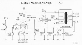
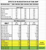
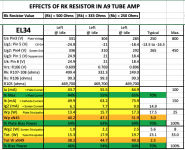
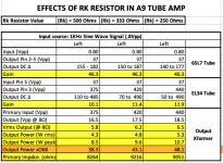
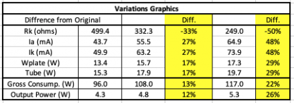
Last time I modified my A9 amp was about a year ago and I experimented with 3 different values for the Rk resistor: 500 ohms (original value), 333 ohms and 250 ohms. I did not try 270 ohms.
I’m posting my measurements with the 3 values for Rk and you can see they are very close to your measurements. I’m thinking 270 ohms might be the ideal value for Rk because, in my case, with 333 ohms felt like it has room to improve and with 233 ohms seems like it’s pushing the tubes too hard. 270 ohms might be the sweet spot. I normally use my amp with Rk 333 ohms and eventually I flip the switch SW to use it with 250 ohms when I want a bit more power.
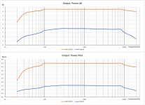
The frequency response has improved a lot with my mods, compared to the original design (See graphics). BTW, these frequency response tests were done using sinewave signals. I’m planning to repeat this test with a squarewave signal, but I haven’t had the time yet.
I hope this information will be useful to you and I would like to hear your (or everybody else’s) comments.
Cheers,
FLima


- Home
- Amplifiers
- Tubes / Valves
- Boyuu EL34 A9 Tube Amp
