It is always plate-to-cathode voltage.If I'm plotting a loadline on a blank datasheet for a cathode-biased, reactive load, such as my power stage, what V do I use?
Is it V=HT, B+, etc ?
or V=HT-(Voltage drop from xfmr DCR primary)=Va (anode)
or V=Va-Vk (cathode voltage drop) ?
Yes, it is a bit tricky to design self-biased stage with just the plate curves. Luckily though, +/-5..10V on the plate don't make big difference in terms of plate current, so you can "assume" some certain middle-of-the-road cathode resistor voltage drop (say, 20V) and OPT voltage drop plus additional PSU sag (say, another 20V in total). That gives you the plate-to-cathode voltage of around 300V, and now you can design from here using the loadlines just like you would for the fixed bias.
Last edited:
Well, by the moment you can see the distortion on the oscilloscope, the THD is already about 2-3%.
And decent DMMs with thermal probe are like £10 nowadays.
I tested this more than a year ago with different cathode resistors, at that time I was thinking it would be nice to get 90% of max dissipation.
Cathode resistor R ----- % of max dissipation
277R -------- 72-75%
340R -------- 70.7%
410R -------- 67.4%
430R -------- 66.5%
469R -------- 64.5%
478R -------- 62%
To be honest, I could not hear the warmer sound by increasing the dissipation, there was difference only because the overall output power increased, this can be easily mistaken as warmth of sound.
I compared with my new push and pull tube amp (Cayin). the A9 is just doing fine, being biased at 60% of max dissipation.
PS: it seems the power supply transformer is OK. at 62% the overall wattage of the device was 86 watt and, at 75% was 101 watt. I pushed the device to work with KT88, that is 120watt of total power consumption, the transformer was just warm after hours of playing
That's good to know.
I'm drumming-up the courage to install 270R,
which, according to LTSpice and this site:
Tube Bias Calc
shows that i'll have 80.4% plate dissipation after all the voltage sagging throughout the circuit.
Also, with my stock KRs the current through the choke is 100mA.
After the swap it'll be 150mA.
I chose to read the current off the choke because the ripple has smoothed down enough to read it directly without messing about RMS, etc.
It is always plate-to-cathode voltage.
Yes, it is a bit tricky to design self-biased stage with just the plate curves. Luckily though, +/-5..10V on the plate don't make big difference in terms of plate current, so you can "assume" some certain middle-of-the-road cathode resistor voltage drop (say, 20V) and OPT voltage drop plus additional PSU sag (say, another 20V in total). That gives you the plate-to-cathode voltage of around 300V, and now you can design from here using the loadlines just like you would for the fixed bias.
Then why is this guy saying
4.1.3 Reactive load and reactive loadline computation - Vacuum Tube Amplifiers - DIY
"A transformer is a reactive load that offers an impedance just when an AC signal goes through its primary. The transformer primary, practically, does not offer impedance when just DC is applied to it. When no signal is applied to the grid, the vacuum tube is in a quiescent state and no AC signal is produced at its anode. In this case, only the DC current goes through the transformer primary and no impedance is seen by the anode. In addition, no signal is transferred from the primary to the secondary of the transformer."
"
My primary has a DCR of 219 ohm - that's about half of my current cathode resistor 497 (500)R. How can he say there's no impedance seen by the anode?
And then, we have Merlin himself stating:
The Valve Wizard -Single Ended
"Choosing a bias point: Because we are using a reactive load rather than a resistive one (i.e., a transformer and not an anode resistor), the bias is not chosen in the same way as for a preamp stage.
The transformer primary has very low DC resistance so only a few volts will be dropped across it, which we usually ignore. Therefore, the quiescent anode voltage will be the SAME as the HT, no matter how much quiescent anode current we choose. We could draw a vertical line at the HT voltage and know that the bias point must be somewhere on it. You can now see that with the load line in its current position, the valve would be biased at cut-off and could only operate in class B!
So, instead of selecting a bias point somewhere on the load line, we slide the load line up the graph, whilst maintaining its gradient. The grey lines show this process. The load line must not go beyond the maximum dissipation curve, and it would be wise to choose a position slightly below the curve for safe running. Load lines for other impedances are drawn in the same way.
We decide that the quiescent anode current we want in this case is 75mA (purple dot), just below max dissipation, and you can see the valve is now operating close to centre-biased Class A (i.e., the bias point is roughly in the centre of the load line)"
Few volts dropped? Mine drops 11v from HT to Anode/plate.
And when biasing close to max dissipation doesn't every volt count?
This is what's confusing me - the language chosen by the pros.
Although i have been using plate-to-cathode in my calcs.
Anyways, here are my latest calcs:
Current "stock" measurements:
Plate-to-cathode voltage=303v
Kr=497ohm / 23.59v drop / 47mA
Plate current=44.9mA (estimated by website)
Plate Dissipation=13.6w @ 54.4% of Max
LTspice shows 100mA across L5 choke
-------------------------------------------------------------------
After installation of 270 ohm KRs:
Plate-to-cathode voltage=292v
Kr=270ohm / 19.68v drop / 72.9mA
Plate current=68.9mA (estimated by website)
Plate Dissipation=20.1w @ 80.4% of Max
LTspice shows 150mA across L5 choke
So...a 50% power demand increase.
Load Line:
Start with the set of plate curves (Pentode/Beam Power curves; or Triode mode curves that you are going to build). If you are using Pentode/Beam power mode, you need to pick a chart that has the screen voltage you are going to use.
1. Pick a Plate to Cathode voltage.
2. Pick a Plate current (for Triode wired mode, this is Plate current + Screen current).
Find what grid bias voltage is at the intersections of 1 and 2.
Then, the output transformer DCR will drop X volts (plate current x DCR; or Plate current plus screen current x DCR for Triode Wired mode).
Decide on an output transformer Primary impedance.
With the plate voltage and plate current (a fixed point at the grid bias voltage you are going to use, calculate Plate voltage / Primary impedance = current increase at zero plate volts.
Add the current increase to the fixed point current.
Mark that current at Zero plate volts on the chart.
Draw the load line (straight) from the Zero plate voltage & current point, to the fixed plate voltage / current / grid bias voltage point, and continue the line all the way to zero current.
That will work for a resistive load.
If you are worried about a loudspeaker load, you just need to decide what output tap to connect the loudspeaker to. For example, an "8" Ohm speaker on the 4 Ohm tap.
Picking a lower output tap makes the speaker damping greater, less variance of frequency response drive to the speaker, the distortion lower, and for the amp to have an easier time driving the loudspeaker's varying load impedance . . .
But, you get less power that way.
You are not going to draw a loudspeaker load line (it is an infinite set of load lines and ellipses).
Did not like the resistive load line results?
Pick a different plate voltage, plate current, output transformer, B+ voltage, different tube, or a combination thereof.
Build a B+ supply that is Plate to Cathode voltage + OPT DCR drop voltage, plus self bias voltage.
Now work on the driver circuit.
Last edited:
That just means that DC impedance (219 ohm) is very small compared to AC impedance (3500 ohm?).My primary has a DCR of 219 ohm - that's about half of my current cathode resistor 497 (500)R. How can he say there's no impedance seen by the anode?
Let's be honest, that A9 amp is quite an compromise from just about all perspectives. 219 ohm DCR is pretty high value, probably adequate for 3-5W and 30-40 mA DC (something like EL84 or 6V6). Even Hammond's 125DSE, which is the cheap "general purpose/replacement" 10-watter with limited bandwidth (100 Hz - 15 kHz at full power), has primary DCR of 126 ohm. "Good" OPTs have much less DCR, so the voltage drop becomes negligible indeed.Few volts dropped? Mine drops 11v from HT to Anode/plate.
And when biasing close to max dissipation doesn't every volt count?
This is what's confusing me - the language chosen by the pros.
That just means that DC impedance (219 ohm) is very small compared to AC impedance (3500 ohm?).
Let's be honest, that A9 amp is quite an compromise from just about all perspectives. 219 ohm DCR is pretty high value, probably adequate for 3-5W and 30-40 mA DC (something like EL84 or 6V6). Even Hammond's 125DSE, which is the cheap "general purpose/replacement" 10-watter with limited bandwidth (100 Hz - 15 kHz at full power), has primary DCR of 126 ohm. "Good" OPTs have much less DCR, so the voltage drop becomes negligible indeed.
Yes, but I look at it this way.
It's an excellent way for someone like me to get into the hobby without the daunting task of putting together a system from scratch. The amps are only as good as the sum of its components and I've changed out lots of parts, added others and gained some functionality it wasn't designed with.
The OPTs are definitely a weak point but I'll swap those or too when the time comes. Basically every time I change something it's like having a new amp. And IMHO it looks great as a decorative piece on the shelf. Better than some hi-fi chassis I've seen that look like they were ripped straight out of a guitar amp. So it's basically a box that we can put whatever inside.
Best thing is even if I screw up and fry it I can just rip everything out and start over. LOL.
Here's something strange:
I put back the original Chinese tubes supplied with the kit and obtained the following readings vs my Russian tubes:
Chinese ............. Russian
(?) ............... (svetlana winged c el34 and Tung-sol 6SL7GT0
B+ 377v................... 336v
B2 355v ................. 316v
Plate 366v ..................325.5v
Cathode 24.88v ................ 23.75v
Plate2Cath 342.2v ............... 302v
I haven't messed with biasing yet - what's going on?
Last edited:
Well, I finally swapped out the 497 (500) ohm cathode resistors for the 270 ohm and I'm now getting 71% plate dissipation but the bass has all but gone.
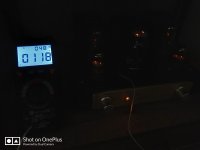
Also...the transformer was getting too hot - I measured it 50C/122F before i switched it off.
Not happy.
I'll put the old resistors back in.
Also...the transformer was getting too hot - I measured it 50C/122F before i switched it off.
Not happy.
I'll put the old resistors back in.
Back to the old resistors.
My readings are now
B+......337v
B2.......317v
Plate.....327v
Plate/Cathode.....303v
Cathode Drop.....23.8v
Back to 55.6% of plate dissipation.
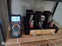
Power meter now reads 88.2w.
It was 104w with the other resistors.
Temp readings below...
My readings are now
B+......337v
B2.......317v
Plate.....327v
Plate/Cathode.....303v
Cathode Drop.....23.8v
Back to 55.6% of plate dissipation.
Power meter now reads 88.2w.
It was 104w with the other resistors.
Temp readings below...
Attachments
Have literally no idea then.No.
Its the same.
Given the output stage current became even marginally bigger (50mA vs 48.8mA) the voltage shouldn't have gone up.
Maybe it's the input stage that is responsible for the effect? Have you tried changing just the input or just the output tubes?
That was kinda expected to be honest...Well, I finally swapped out the 497 (500) ohm cathode resistors for the 270 ohm and I'm now getting 71% plate dissipation but the bass has all but gone.
Also...the transformer was getting too hot - I measured it 50C/122F before i switched it off.
Hmph...even at stock biasing my tranny runs at 52C/126F.
Yeah, that thing with swapping out the tubes for the originals and my Rail bouncing up 41V has left me scratching my head.
So, is it worthwhile upgrading the OPTs for 6.6K/15W? I know that the greater impedance will rotate the load line anti clockwise with or without more biasing and get me more swing.
Do you this will hold on to or even improve the bass?
Last edited:
That'll give you slightly more voltage swing and significantly less current swing, so less output power in total. I would stick with something in the 3-4k range.
BTW, while 6.6k is pretty common parameter for PP transformers, I've never seen SE ones with that impedance.
BTW, while 6.6k is pretty common parameter for PP transformers, I've never seen SE ones with that impedance.
Ah..
Glad you said that.
The custom supplier i'm in contact with might be assuming its a PP.
Well, without knowing for sure, it seems the original OPTs are 3.5K..
Whats left? Chunkier for more power?
Glad you said that.
The custom supplier i'm in contact with might be assuming its a PP.
Well, without knowing for sure, it seems the original OPTs are 3.5K..
Whats left? Chunkier for more power?
I'm not actually sure that upgrading the OPTs is very useful given that PT doesn't allow to bias the tubes hotter. You'll get maybe extra 5% power, and that's about it.
So I would either leave the amp as it is or upgrade the PT first.
Another thing you can do is switching to SS rectification to boost the B+ voltage (you'll probably have to replace the electrolytic caps too though).
So I would either leave the amp as it is or upgrade the PT first.
Another thing you can do is switching to SS rectification to boost the B+ voltage (you'll probably have to replace the electrolytic caps too though).
There's a big 33R resistor between the tube rectifier's cathode and the reservoir cap. Removing that would bump up the B+ by 12v.
Correct me if I'm wrong, but don't single ended amps consume at least the same power idling, supplying the biases as they do playing music?
Regardless of the PT, I know I can't expect more than about 10w output anyways, right?
In any case, I'm looking for a more solid bass response, hence chunkier OPTs.
You recommend 4k?
Edit: Hey, thanks for all your help. It's much appreciated!
Last edited:
33R resistor is there to limit current pulses that are charging the first reservoir cap. 5Z3 allows for 4uF max without the resistor, and you probably have 22uF, so leave it where it is.
Replacing the 5Z3 with a couple of SiC Schottkies (even with ultrafasts if you don't want to pay much) will raise the B+ to 400+ volts (probably around 420V), so you can increase the power without the additional stress on the PT (keep the same ~50mA bias, and the PT's life will be easier by 12-15W that are heating the 5Z3 now). You'll need the 500V electrolytics though.
For OPTs I'd recommend 3-3.5k. And yes, you can improve bass response with better OPTs, that's for sure.
You're welcome!
Funny, I already have ultrafasts (UF4007) in series with the rectifier tube.
Guess I could just remove it and short the pins.
But..aww.. the aesthetic is also important, lol.
That amp is going to look horrible with an empty socket.
Furthermore, I'd be creating a bastardised Frankenstein of a monstrosity that is neither tube or silicon, lol.
(I hope @6A3sUMMER reads this - I know he got a lot of stick scores of posts back for using SS power supplies in his amps).
But seriously.. nah.
Can chunkier OPTs still work out?
I know the maker's of this amp offer an assembled version with bigger OPTs - ones that sit atop the chassis with bell housings.
No idea what their specs are, though. And I assume all else is equal.
- Home
- Amplifiers
- Tubes / Valves
- Boyuu EL34 A9 Tube Amp