Hi eddyvinyl,
these tubes are identical. What can I say about the quality - I coupled this amplifier with Klipsch R-28F. Then I started hearing every wire, capacitor and resistor in this amp. Then I made 100 experiments, changed the schematic somewhat, coupled it with a Jlabs ODAC and... well, I have an amazing sound. Some time soon I'll write down my outcomes.
these tubes are identical. What can I say about the quality - I coupled this amplifier with Klipsch R-28F. Then I started hearing every wire, capacitor and resistor in this amp. Then I made 100 experiments, changed the schematic somewhat, coupled it with a Jlabs ODAC and... well, I have an amazing sound. Some time soon I'll write down my outcomes.
I've done a bunch of mods as well. Wonderful sound into my OB speakers which are 2 EV LS12's and a 15" Hawthorne Audio Augie in each channel. The Augies are run off plate amp. Also have used them with Caintuck Audio Betsy's (8" fullrange), which also sound great.
Biggest change was adding some internal feedback. I'll comment more on this later when I have time.
Dave 😀
Biggest change was adding some internal feedback. I'll comment more on this later when I have time.
Dave 😀
Hi all,
I just have bought a Boyuu A9. Its for playing and learning and having fun.
I'm a newbie in tube amp DIY, but I think I will get it with this fantatisc thread.
My kit misses some cables and some hints for cabling.
What diameters and shielding do you use?
What isolation is needed for HV?
Regards to all
Josef
Hi hurdy_gurdyman,
could you please share how did you implement the feedback (schematic)? I tried a few very different levels of feedback and I did not like the resulting sound, so I just pushed the EL34 to work harder to get better bass.
could you please share how did you implement the feedback (schematic)? I tried a few very different levels of feedback and I did not like the resulting sound, so I just pushed the EL34 to work harder to get better bass.
Last edited:
Hi hurdy_gurdyman,
could you please share how did you implement the feedback (schematic)? I tried a few very different levels of feedback and I did not like the resulting sound, so I just pushed the EL34 to work harder to get better bass.
I got rid of feedback altogether but I did fine GFB the best a 1.5m resistor from pin3 of el34 to pins 3,8 of the 12ax7 or pins 3,6 on 6N9P I changed the 6n9p for a russian 6H9C a much better sounding preamp valve, get rid of the 470uf cap on cathode preamp and I found it to sound good. the pic above someone else posted is my first build of a kit I brought from china. I mod it totally wasn't happy with sound I replace it with this schematics which I will post later. What I also found was a good pair of xovers in my 4 way speaker boxes brought the bass up so I have a punch for bass. I made my own xovers and have low bass at 350hz mid bass at 550hz and midrange / tweeter at 4000hz I wound all my own chokes inductors and the bass is a punch and mid is excellent I play old vinyl records and every symbols Is heard.
Attachments
Last edited:
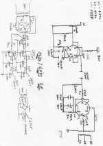
Well, I spoke with several people on this before doing anything. This is what I came up with. I tied the plates of the EL34's to the plates of the 6SL7's using 400k resistors (had a bunch of 100k resistors I tied together), and used 33k resistors to tie the plate of the 6SN7 to the screen grid. This makes a much tighter bass than the stock unit. The penalty is a good sized loss in gain. I am using a tube preamp, so didn't have a problem with it.Hi hurdy_gurdyman,
could you please share how did you implement the feedback (schematic)? I tried a few very different levels of feedback and I did not like the resulting sound, so I just pushed the EL34 to work harder to get better bass.
There are more mods to do when I have more time this winter.
Dave
Hi guys!
mdamp, I've connected the EL34 same as you. It seems you've decided to push the 6Н9С to a much more stressful current, I would guess at least 3mA at idle.
Hurdy_gurdyman, from your description I'm left with the impression that you ended up with a completely unseen preamp-to-amp circuit. I imagine 400k between 6N9P's plate to EL34's plate and 33k between the 6N9P's plate and the EL34's screen grid.
What I found after a lot of struggle with "histerical" mids and highs is that the cathode bypass capacitors, when electrolytic, behave very strangely with very low voltages and very small changes in current as in the original schematic with 2k/100k resistors on the 6N9P. After testing all possible capacitor technology on earth, for a great surprise, tantal capacitors were the ones that are absolutely transparent to me. I ended up using 22uF 10V cap and a cathode resistor of 1.8kOhm.
With a cathode resistor of 330 Ohms the EL34s are adequatly biased to provide a stable bass output. The higher current significantly lowered my B+ from 325V to around 300V, but I decided I won't think about the power transformer... I really like the sound right now.
Sorry guys but I also bought russian 6Н9С (which turned out to be a perfectly matched pair without being matched 🙂 ), but the only difference that I hear from the chinese tubes is just slightly better gain. I guess my chinese tubes are a very good pair...
The 33k resistor is between the 6SL7 plate back down the 6SL7's grid, not the EL34's grid.Hurdy_gurdyman, from your description I'm left with the impression that you ended up with a completely unseen preamp-to-amp circuit. I imagine 400k between 6N9P's plate to EL34's plate and 33k between the 6N9P's plate and the EL34's screen grid.
Also, forgot to mention that I had earlier bypassed the volume control and changed the grid-to-ground to 100k resistor (had a Bunch of 100k resistors 🙂 ).
Dave 😀
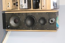
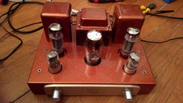
Hi jassenjj I have change a few things in my last schematics the power transformer and it seems to work fine for me sound is excellent punch bass I maybe pushing the tubes abit but I'm happy doing this.also here is the speaker system I'm running it through. cheers
Attachments
Hi all, I just got an A9 kit. I put it all together with a number of the mods listed throughout this thread. I just powered it up for the first time and I'm getting 460V at B+. C301 and C303 are 22uF and C302 is 180uF. Ideas?
"Help ! I need somebody..."
Hi guys !
I am trying to build a A9 amp with a friend (that knows well about audio electronics). We have been working a lot on it. We already try changing the transformer, and the 5z3pj tube.
So for here are the different results :
1) The transformer seems to melt and produces smoke, that is usefull if you want to produce smoke, useless if you don't.
2) The fuse breaks at start, that is usefull if you want to break some fuses, useless if not.
3) The transformer starts, no heater glow, no sound at all, that is usefull if you want a silent amp, not if you don't want a silent amp.
I have already read all the 30 pages, and I would have some questions :
1) Is it possible to test the main power block. So it possible to just wire the transformer to 5z3pj tube, the power switch and no nothing else ? Because we tried and it didn't worked (smoke, broken fuses etc...). And I would be very happy just to see a glowing heater.
2) When we read ground on the schematics, are we right about wiring to the middle hole of the power cable ?
I would have done some pictures, but for the moment, a lot of components have been desolded to test the main power supply...
Transformers that 'melt and produce smoke' may be damaged and not safe/suitable to be used.
You need to power up just the transformer using a DBT (dim bulb tester). All secondaries are to be disconnected while testing.
With the transformer powered up, the bulb should be out (not lit), and if you get this far then you should measure, identify and confirm all the secondary voltages are OK before continuing any further.
With the very greatest respect, it sounds like you need to seek more professional help in wiring the power supply and in correctly identifying earth and ground locations.
The voltages produced by the transformer are potentially deadly... you have to be sure of what you are doing.
I'll second what Mooly has said. Once a transformer has smoked, it is probably bad. Certainly not trustworthy.
If the fuse blew open, why did you continue with it shorted (or much bigger fuse installed)?
You need to stop and let someone who is a technician look at what you have.
-Chris
If the fuse blew open, why did you continue with it shorted (or much bigger fuse installed)?
You need to stop and let someone who is a technician look at what you have.
-Chris
If the fuse blew open, why did you continue with it shorted (or much bigger fuse installed)?
You need to stop and let someone who is a technician look at what you have.
-Chris
Each time a fuse blew, I replaced it with a new one.
Thanks for reminding me that it can be dangerous, but I already aware of that, and be sure that we pay attention.
"You need to stop and let someone who is a technician look at what you have." ----> that's why I came here 🙂
Once each transformer wire has been checked, is it possible to put 5z3pj bulb in place and power it up ? (4 pins wired)
Once each transformer wire has been checked, is it possible to put 5z3pj bulb in place and power it up ? (4 pins wired)
Yes, but first you must check the transformer you have fitted is good and that it is producing the expected voltages before you connect the valve to it. The fact it smoked means that the insulation may be damaged... and that could be dangerous. It has been stressed way beyond its limits to reach a 'smoking and melting' stage.
If you are still not sure how to do that, then you must ask someone who knows to actually show you how its done. That is what Anatech is saying above. You can not afford to get this wrong because of the safety implications.
Hi ! I tried to check the transformer with a micronta 22-211, that obviously doesn't work anymore. So while being completely desperate, I tried to invert pin 2-8 and 4-6 wires, and now 5z3pj bulb lights up !
Now I have put everything back in its place. When I turn the power on, I have a little sound coming of the speaker, but nothing else (I mean not the music I pluged in).
I see no light coming from the 6n9pj tube, is it normal ?
Could someone confirm that wiring from the input signal panel is right ?
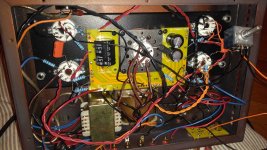
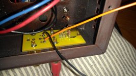
Here is some pictures in attachment :
Please note that everything has been soldered and unsoldered and soldered...to check everything. So yes it looks like a real mess, but I promise it was nice at first...)
Now I have put everything back in its place. When I turn the power on, I have a little sound coming of the speaker, but nothing else (I mean not the music I pluged in).
I see no light coming from the 6n9pj tube, is it normal ?
Could someone confirm that wiring from the input signal panel is right ?
Here is some pictures in attachment :
Please note that everything has been soldered and unsoldered and soldered...to check everything. So yes it looks like a real mess, but I promise it was nice at first...)
Attachments
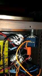
I think you are being a bit optimistic to expect someone to try a decipher it all from photos tbh 🙂
No light from the 6N9. Some filaments can be dim and not very visible, and so without knowing you are going to have to measure the AC voltage ACROSS pins 7 and 8. You should have between 6 to 7 volts AC. The valve should be quite warm after a couple of minutes as well if the heaters are powered.
That is the first thing to check.
Then measure and record the DC voltage on all the other pins (including pins 7 and 8) and report back.
- Home
- Amplifiers
- Tubes / Valves
- Boyuu EL34 A9 Tube Amp