I believe that the data about those vintage capacitors has been published on paper only. I remember the databook but I threw away my copy many years ago. On late '90, a CD-ROM was published with Philips semiconductor databooks but I should check if there were any of these passive components. By the way, the Philips capacitor business has been sold to BCcomponents in 1999 and is now Vishay. Any Philips branded capacitor is at least 18 years old. They seems to age well, I never replaced any on my vintage gear, but since your amplifier is new and you already bought new capacitors, you may as well use the new parts. I use Vishay axial electrolytic capacitors to restore tube radios, they still retain the vintage look.
For everyone experiencing hum with this device - I just realized that the paint on the chassis is so thick, that actually the different components are not connected to ground.
Here are the components that left without an electrical connection to grounding (and inbetween themselves) after I connected the grounding pin to one of the 4 screws on the plate carrying the tubes:
- power transformer body (!!!);
- choke;
- chassis;
- OPTs and their steel housing.
I could actually measure electrical connection only between 2 of the metal holders of the tube sockets, everything else remained from the chassis remained isolated. Now I'm destroying the paint here and there in order to connect the different components to ground.
Why should all the iron's be "connected" to the chassis, since the chassis should not really be used for ground in any case...
Hey jazbo8,
my other equipment has grounded chassis (my PC for instance), I don't want potential differences on the RCA input, so the schematic's ground is connected to the chassis.
I really hope that you are not OK to have high voltage appliance with metal body whose different human accessible parts are not grounded and not connected between themselves, making it possible to have potential differences between them of hundreds of volts.
Last edited:
Yes, it should only occur at a single point. It's usually not a good idea to use the chassis for the common ground connection.so the schematic's ground is connected to the chassis.
Well, it's now 2-point centered. One very ugly place which gathers all wires connecting the different chassis parts to ground which is connected to the single schematic ground on the board.
Still, the body of the power transformer is isolated, once finished I'll check if it needs to.
Still, the body of the power transformer is isolated, once finished I'll check if it needs to.
I once had an output transformer that had a short from the primary to the transformer frame.
That is a real good reason to have the frame grounded, unless you like to be shocked.
The same goes for the output taps. Ground the common tap, so if there is a primary to secondary short, you will not be shocked.
That is a real good reason to have the frame grounded, unless you like to be shocked.
The same goes for the output taps. Ground the common tap, so if there is a primary to secondary short, you will not be shocked.
Well, I finished it. Sounds really nice, I am quite impressed actually with the amazingly low level of noise that I achieved and with the output power. I am impressed. My 2x75W 6 Ohm speakers from my Panasonic mini system are quite loud with this amp.
Here's what I "improved":

- connecting what I could from the different metal parts to ground;

- on the pictures the 2 yellow capacitors (jb JFGC 2.2uF 400V) are parallel to C302, connected closest to the OPT input points;
- the 2 red capacitors are 1uF, 400V parallel to C303, connected closest to R103, R203;

- C302 is replaced with a fat short cap, Panasonic HB 180uF, 400V height 30mm, diameter 30 mm. Fits perfectly, any other size would be too much for the space. This is not produced anymore from Panasonic, but there are higher capacitancies from other good brands. You just need to make the snap-in legs thinner, it's kind of tricky.
- EL34's g3-s are connected to ground (just a habit, I prefer ground instead of cathode). One side of the heater is connected to ground;

- preamps' heaters are connected with a mid point with stuff I had around, take a look at the schematic;
- C103, C203 are replaced with audio caps, 330uF 63V. I just already had them...
- parallel to R104, R204 I put 100uF, 25V audio caps;
- added 0.5A fuse in the cathode circuit of the diode and a beefy 4uf non polar motor cap to handle the current in case of a short from filament to anode;
- after a few hours of listening and some measurements, I removed R301. I hear no ripple whatsoever so just dissipating some heat is not justified. Hopefully the diode will handle 38uF directly connected to it easily.
- the Russian 6Н9С that I bought produce really nice, somewhat better, "stronger" sound than the 6N9PJ.
Here's what I "improved":
- connecting what I could from the different metal parts to ground;
- on the pictures the 2 yellow capacitors (jb JFGC 2.2uF 400V) are parallel to C302, connected closest to the OPT input points;
- the 2 red capacitors are 1uF, 400V parallel to C303, connected closest to R103, R203;
- C302 is replaced with a fat short cap, Panasonic HB 180uF, 400V height 30mm, diameter 30 mm. Fits perfectly, any other size would be too much for the space. This is not produced anymore from Panasonic, but there are higher capacitancies from other good brands. You just need to make the snap-in legs thinner, it's kind of tricky.
- EL34's g3-s are connected to ground (just a habit, I prefer ground instead of cathode). One side of the heater is connected to ground;
- preamps' heaters are connected with a mid point with stuff I had around, take a look at the schematic;
- C103, C203 are replaced with audio caps, 330uF 63V. I just already had them...
- parallel to R104, R204 I put 100uF, 25V audio caps;
- added 0.5A fuse in the cathode circuit of the diode and a beefy 4uf non polar motor cap to handle the current in case of a short from filament to anode;
- after a few hours of listening and some measurements, I removed R301. I hear no ripple whatsoever so just dissipating some heat is not justified. Hopefully the diode will handle 38uF directly connected to it easily.
- the Russian 6Н9С that I bought produce really nice, somewhat better, "stronger" sound than the 6N9PJ.
Attachments
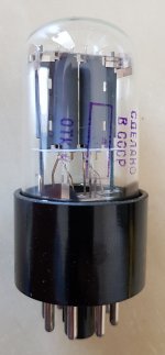
Oh, and I forgot the grid stopper resistors - 4x 3.3K and one 680K bleeding resistor. I just couldn't resist the temptation to put this МЛТ-1 stamped with year 83 inside next to the tubes with a date stamp III 77 which were used for the first time 40 years later 🙂
Nice build! Thanks for sharing.
If you want to be compliant with the safety requirements EN60055, the capacitor C304 between the mains switch contacts must be X2 rated (with the CE logo stamped on it), and there should be a guaranteed minimum distance between the electrical connections on the primary side of the transformer and all the other components and wires. You may secure the wire that goes to the power switch to the chassis with glue or fasteners, and/or use a conductor with double insulation.
I believe that R301 has been put there to lower the peak current in the transformer winding, and therefore the transformer temperature. You may check the temperature after a few hours. What values you used for R103 and R104 (preamp anode and cathode)? What is the voltage at B1 (after the choke)?
Hi pcan,
you're right - I have forgotten that this resistor could be there just for this particular reason. The transformer gets pretty hot, but I cannot tell any difference with or without R301. Without R301 the voltage after the choke is 328V with R301 - it's 324V so I restored it back in place.
I ended up using the values from the schematic - 2k for R104 and 100k for R103. I couldn't "hear" any difference with 1.5k for R104 and 68K for R103 (with all 4 combinations with the original values) - probably it only changed the position of the volume control before the beginning of the clipping.
The added capacitor in parallel to R104 changes things *a lot*. The amplification is really boosted and the bass becomes somewhat exaggerated - the lack of feedback becomes too obvious. I might end up dividing R104 to 2 resistors - 1k in parallel with a cap and these 2 in series with 910 Ohms to lower the effect of just omitting the cap. But this will only happen if better loudspeakers like Klipsch R-28Fs prove it is necessary. I really enjoy the newly discovered dynamic in some of the recordings I believed I knew in absolute detail.
When it comes to the voltages of the cathodes of the 4 lamps - in my terms for accuracy they are disastrous, but I guess it's OK with tubes 🙂 The 2 channels sound really equal to me. Given that R104/R204 are almost identical at 1970 and 1973 measured ohms one channel has 2.3V on the cathode, the other 2.17V with the 6N9PJ-s. The cathodes of the EL34s are 21.5 and 22.9 volts respectively (the resistance is again equal around 493 ohms of the paralleled R107, R108 and R207, R208).
I observe something unexpected with these tubes. They ring ... I mean you can hear the big tubes ringing physically when the input is silence. Sometimes I believe I can hear this through the loudspeakers with more metal sounds. Has anyone of you ever experienced something similar? I have never heard something like this mentioned somewhere...
All in all, I would conclude that I have a really fresh and crispy sound that I really enjoy and makes everything sound nice. The specific depth and ambient of everything that sounds through tubes is definitely there... I actually hear difference in the sound after 30+ hours of listening - it became less pinchy and more balanced. Maybe this thing with "breaking in" the tubes, caps and so on is a real process - all the tubes that I have listened to (and they are many) were all old devices so this is new for me. Something definitely happened to the sound and I like it more and more.
Please excuse this unconnected post.
I have been discussing through ePay's messaging the BOYUU A9. We were exchanging modification ideas. I decided to go to email and tried to give it to him. I was banned for 10 days.
Anyway, if Pete, if you are lurking, please PM me.
Dave
I have been discussing through ePay's messaging the BOYUU A9. We were exchanging modification ideas. I decided to go to email and tried to give it to him. I was banned for 10 days.
Anyway, if Pete, if you are lurking, please PM me.
Dave
Your voltages seems to be OK for this amplifier. On my power transformer, the filament supply is exactly 6.3V when the primary voltage is 220V. This is the mainland China standard, slightly lower than most EU countries. I also tried several working points for the preamp tube Gain and distortion of the stage changes, but I don't notice any real difference either. The output tube ringing you describe is strange. There may be a ultrasonic oscillation on the preamp or output stage, but usually this also means a low/distorted output or excessive current draw on output tubes. Is it a mechanical vibration? Does it come from both tubes, and is it related to certain positions of the volume potentiometer?
Well, I played around with that ringing. It is not always there, it comes from the rectifier and the EL34s up to 20 minutes after turning on the amp from cold. It's not RFI or oscillation of some kind, I know the collateral effects if this was happening. It's purely mechanical ringing like if some part of the tube's construction is too loose before reaching its full thermal expansion. And yes, when it's happening - the high end of the output is "colored" with this ringing but only some specific drum/metallic sounds - a partial internal microphony of some kind happens.
Given that it disappears after 20 minutes of operation and is barely audible, I can live with it 🙂 Most probably it'll disappear with other tubes.
Given that it disappears after 20 minutes of operation and is barely audible, I can live with it 🙂 Most probably it'll disappear with other tubes.
Hi guys,
one general question. When it comes to the voltage rating of the filtering caps - all of them are 400V, but during startup I've measured voltages up to 430V before the choke.
What do you think? Should I be concerned?
one general question. When it comes to the voltage rating of the filtering caps - all of them are 400V, but during startup I've measured voltages up to 430V before the choke.
What do you think? Should I be concerned?
How long does the 430V spike last? Electrolytics can handle sitting over their rated voltage, but not for all that long!
Well, I would take the time to figure out what the part number is for the cap seeing 430V, then check the datasheet to see if there's a surge spec.
450V caps are so easy to find and so inexpensive that it seems silly to take chances with something like this.
450V caps are so easy to find and so inexpensive that it seems silly to take chances with something like this.
Hi,
I bought a Boyuu A9 amplifier ready. The 6SL7GT tube, if I install it compatible without conversion to the amplifier?
How much better is your voice?
Thannks,
I bought a Boyuu A9 amplifier ready. The 6SL7GT tube, if I install it compatible without conversion to the amplifier?
How much better is your voice?
Thannks,
- Home
- Amplifiers
- Tubes / Valves
- Boyuu EL34 A9 Tube Amp