Thanks Dave. For some reason, I have forever had an interest in these sorts of things and get an AHA moment when I saw your internal TL. Wish that I had money, time and youth to experiment with.
Yes, it's a rather unusual arrangement. Here are some details: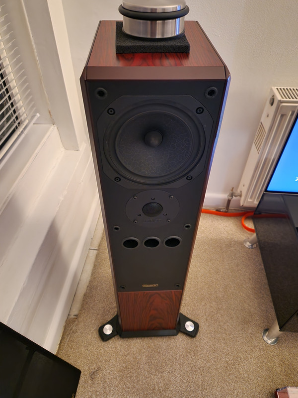
4 vents is a bit weird. The tweeter is quite interesting (i guess it is a superTweeter given what looks like a tweeter at about knee height under the woofer. Note that given the XO of a superTweeter, it should be as close tothe tweeter as possible.
This loudspeaker will be an ML-TL given the aspect ratio of the box, the placement of the woofer, and vents. From the vents placement one would suspect that the designer didn’t know that (where is the one on the back?)
I am not a big fan of foam for damping*, but it does not need to be firmy attached, but it shoulod be sliceable such that it iis friction fit. In an ML-TL damping can range from lining of the walls, to completely filling it will some variety of polyfluff.
*(i like using it foraperiodicm venting.)
How is the bass? What are the internal dimensions? How far from the bottom are the vents? Distance of driver centre from top.
Without the T/S of the driver it is not really possible to simulate it, but someone like Scott (@Scottmoose) can probably offer some inights intothe resonant structure in the box.
One start to specualte how one could rejug all the bits to get better performance.
dave
https://www.dutchaudioclassics.nl/img/brochures/Mission-752f.pdf
I like the bass and have no issues with it. The rear port is not that far off the ground, so much lower than the front ones.

It's a double-chamber reflex (DCR), with some asymmetry to the venting. The larger upper chamber has the three forward-facing ducts, and it vented internally to the smaller lower chamber through five or six (IIRC) holes that were simply of panel-thickness length. The lower chamber had a single rear-firing duct to the external air. As a minor addition, the larger upper chamber had a longidudinal panel open at the top & bottom (since this was nominally a Helmholtz design). Mission described this as their 'Transverse Folding Technology' -which speaking under correction was basically a synonym for a bracing panel for the side baffles. 😉
From the measurements I've seen, it's classic DCR: unequal triple impedance peak, and the usual cancellation null just above the nominal second tuning. Presumably the asymmetry of the 'external' venting was to maintain some visual connection with its 752 predecessor and they'll have juggled the proportions of the holes in the internal baffle to avoid the need for an extra duct there, and reduce the requirement for more on the rear. This is mid-larger scale commercial audio, so saving a pound or so makes sense when possible. What measurements I've seen, from memory, suggests to me it was slightly detuned / or not optimally so anyway, resulting in a bit more cancellation from that cause than you'd hope for, though it wasn't terrible: a reasonable tradeoff in the eternal performance / profit scale.
From the measurements I've seen, it's classic DCR: unequal triple impedance peak, and the usual cancellation null just above the nominal second tuning. Presumably the asymmetry of the 'external' venting was to maintain some visual connection with its 752 predecessor and they'll have juggled the proportions of the holes in the internal baffle to avoid the need for an extra duct there, and reduce the requirement for more on the rear. This is mid-larger scale commercial audio, so saving a pound or so makes sense when possible. What measurements I've seen, from memory, suggests to me it was slightly detuned / or not optimally so anyway, resulting in a bit more cancellation from that cause than you'd hope for, though it wasn't terrible: a reasonable tradeoff in the eternal performance / profit scale.
Last edited:
Here's something to read.
ESP box filling
Also, the lower the box tuning the less problems with reflected garbage.
ESP box filling
Also, the lower the box tuning the less problems with reflected garbage.
Put your Phone (or even a small speaker) on music or sweep and put it into the enclosure, mount the driver. Listen (or even measure) what comes out where from the enclosure...
+1. Yup, that's how we used to do it pre-phone years--throw a radio in there. Also put it on it's back and pull the woofer screws and work through the hole messing with resistive materials while it's running. Yeah it leaks, but you're not going after damping -- you're fighting box mud, standing waves, reflections from walls through cone etc. MInutiae about precise analogs of excitation are moot once you follow your ears. Choose (a) voice (b) heavy percussion, and (c) big soundbodies like cello, etc. Find the best compromise for all 3 and button it back up.
You only get notification if an "@" is added: @krivium @Freedom666i don't get notification if not accurate spelling
once you type @ and the first letters the forum software proposes available names - good for correct spelling!
Interesting, thank you.It's a double-chamber reflex (DCR), with some asymmetry to the venting. The larger upper chamber has the three forward-facing ducts, and it vented internally to the smaller lower chamber through five or six (IIRC) holes that were simply of panel-thickness length. The lower chamber had a single rear-firing duct to the external air. As a minor addition, the larger upper chamber had a longidudinal panel open at the top & bottom (since this was nominally a Helmholtz design). Mission described this as their 'Transverse Folding Technology' -which speaking under correction was basically a synonym for a bracing panel for the side baffles. 😉
From the measurements I've seen, it's classic DCR: unequal triple impedance peak, and the usual cancellation null just above the nominal second tuning. Presumably the asymmetry of the 'external' venting was to maintain some visual connection with its 752 predecessor and they'll have juggled the proportions of the holes in the internal baffle to avoid the need for an extra duct there, and reduce the requirement for more on the rear. This is mid-larger scale commercial audio, so saving a pound or so makes sense when possible. What measurements I've seen, from memory, suggests to me it was slightly detuned / or not optimally so anyway, resulting in a bit more cancellation from that cause than you'd hope for, though it wasn't terrible: a reasonable tradeoff in the eternal performance / profit scale.
I would have never thought of that. Thank youPut your Phone (or even a small speaker) on music or sweep and put it into the enclosure, mount the driver. Listen (or even measure) what comes out where from the enclosure...
I am sure it's not the greatest speaker on the planet but after a number of unsatisfactory (and expensive) trials involving active designs from Kef and B&W, this replaced a pair of LS3/6's from Stirling. Long last I enjoy listening to music again hence I am trying to get them to sound their best (with the amplification I have at hand). Grateful for all the incredible advise and knowledge here.
Small bluetooth speaker is good to test this stuff, has bit wider bandwidth than just the mobile but I guess mobile is just fine especially for the smaller speakers. Funs tuff experimenting with mobile speaker.
And it's not just the cone that "leaks", next time you are building a box don't cut the hole on the baffle yet so that it's just a box without any holes. Lay it on the back and use a loose panel thats not glued yet like a lid on a chest so easily opened and closed. Put mobile speaker inside the box and measure with SPL meter or RTA a reference the lid open. Repeat lid closed and it attenuates only few db, and sure enough it's loud to ear as well, as if the lid made almost no difference, especially if it leaks any. Put some damping material in the box and hold the lid down and it really gets quieter. These kind of real time tests are great, as the difference is easily seen and heard and tweaked so some kind of understanding about magnitude of things form.
Someone suggested take the driver out and just sing into the speaker hole and listen how the box sounds, I'd imagine standing waves are easy to hear if problematic, and they'd likely be problematic with the woofer making the sound in there as well. Great test I think, at least fun if nothing else, family gets some fun time dad bottoms up head in the box making funny noises🙂
Another is using the driver as microphone hooked into your sound card input, then go and tap the box panels and try to figure out how what you perceive translates to measurement. Hear the panel ring with knocking? can you see it in the measurement as resonant peak? Same would work in reverse, speaker playing the panel would ring.
Anyway, whatever the testing the most important thing is that there is some, and that one tunes the system with best intention based on the observation. I bet it's quaranteed better result, less box sound, than just doing something based on internet people saying they had done and never tryign to compare to anything else.
Last edited:
I'd remind members that this member paging method should be included before you post. Edits don't count.. but this may change in the future.You only get notification if an "@" is added:
I've been thinking about this... two problems
1) inbox resonances and modes affecting driver response (nearfield measurement)
2) box panels emitting sound (nearfield and farfield measurements in 3D)
For both we need a way to measure the frequency distribution and magnitude of disturbancies. Distortion and decay too. Slow sweep is best. Listening is fun, but you can notice only gross changes.
For 1) source and mic location is crucial, small changes make huge differencies in inbox measurements. Inserting coatings, wool, braces etc. will change everything. I would simply just measure the driver in wide baffle without a box first, then compare it to measurements when installed in the box and with fillings etc.
2) Panel resonances measured with accelerator vary per sensor location, and magnitude translation to farfield sound is questionable. What is the best excitation - driver's sound or a knock? I'd really like to know more about this (real measurements of modifications with eg. Klippel NFS, highest resolution). So far I just rely on traditional recommendations and knocking the box.
I have measured and modded JBL LSR305 cheapo speaker boxes... https://www.diyaudio.com/community/threads/jbl-lsr305-tweaking.320206/
Last edited:
‘Reflections’: that is a broad definition. The ‘resulting’ standing waves in the cabinet are of interest though. They appear through cones and ports. And do show in frequency response, decay plots and often in impedance plots of the driver concerned.
I've tried to absorb rear reflections on most of my projects, and it seems to help, but not all of the "boxy sound" comes from the reflections, some will come from the cabinet vibrating.
I've now added the foam to the upper enclosure. Solid cast driver and again, nice to see proper bolt and nut fixtures rather than wood screws! Internally, damping was minimal in the upper enclosure with only some mastic sound deadening pads applied to the side walls and foam attached to the rear. There is cross bracing as well as a division with holes which, underneath (lower enclosure) is damped with foam. The cabinet walls seemed to be veneered inside too and thick, an inch by my estimate. I have cut the 5 cm foam to size so in now is the width of the internal cabinet and extends approx 3/4 down the upper enclosure, half way between front baffle and rear wall ie. free in space, leaving the front ports unobstructed.
The result, listening to voices only (BBC Radio) is fuller, more direct with less of that (very slight) hollow/resonant sound I commented on before. I was nitpicking before as I really liked the sound already but it is definitively audible (or not audible anymore more correctly). I acknowledge this is a highly unsophisticated method with absolutely no measurements, but it's the best I can do for the moment and I am very happy with the result. The side walls immediately to left and right of the driver are still bare and I may try and put a little foam there too, leaving the side vent structure of the driver unobstructed but for now I will just try and listen to some different material, then evaluate.
My next job on the speaker is the wiring. There is likely nothing wrong with it but my OCD is calling to re-wire with something slightly nicer ... I know. I would also like to get a nice stainless steel back plate with good quality non-biwiring terminals.
Thanking all of you which have assisted me with this kindly. It really is appreciated.
Last edited:
After listening to music I have the impression that transients are now slightly compressed. Now I am not sure if this is the more accurate version but it takes a little bit of ‘fun’ out of the equation. Not too much but its noticeable. Great for timbre, a little bit less for PRAT. I will perhaps try and cut the foam to a round shape, matching the driver basket in its entire width and attach this directly to the magnet. As is, it (foam) forms a complete division between driver and rear wall, open only downwards.
My guess is it impedes the air flow to the driver somehow even though my belief was, probably wrongly, that open cell foam shouldn't do this.
The other option, as mentioned before, would be to just use foam in strips all around the driver inside the front baffle, leaving some gaps for venting.
Fun times 😀
- Home
- Loudspeakers
- Multi-Way
- ‘Boxy colouration’ or internal reflections through cone