The previous answers are all great. My two cents, or maybe it's a dollar with inflation. It's not very scientific but I find pulling the driver out and then just singing a range of notes into the opening for the woofer will immediately reveal any resonances that cause boxy vocals directly to your ear. If you own a dog, it may join in with a howl. You can also place a speaker near the empty opening and drive it with a generator and slowly sweep through the frequencies. I find that the Hornresp free software can model a cabinet cavity and accurately calculate and plot the internal acoustic resonances. It also has the ability to model added damping with adjustable thickness against the walls. You will quickly find that longer / slender cabinets have a low internal mode frequency that is very difficult to damp as damping material effectiveness drops off at low frequencies (below ~ 300 Hz or so ). I only build half cube shaped enclosures for this reason. I've found that rockwool, fiberglass batting, lambswool and engineered fire retardant acoustic foam all work. The effectiveness is proportional to the density, so the acoustic foam works, but due to its fixed density, is the least effective. The others can just be packed in as loosely or tightly as desired. As velocity is zero at a wall surface (perpendicular to the wall) only putting thin layers on the walls is less effective than filling the open space. Adding stuffing to ported speakers will lower the Q of the port and reduce the output. It works well to put fiberglass or rockwool into a fabric bag to make an acoustic pillow that is easy to place or remove.

I use a U shaped baffle made from a section of R13 rockwool hung behind the driver. Its suspended by shoelace material so it hangs firmly behind the driver basket. If the driver has an exposed VC gap which could be susceptible to loose debris or particles getting inside, i use a piece of grille cloth to contain the dampening material.
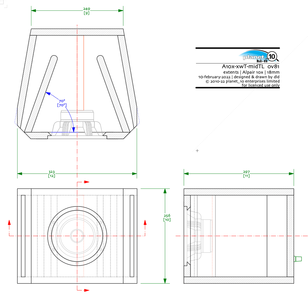
For new designs, I also build internal baffling to break up parallel walls, as seen in the rough sketch below.
For new designs, I also build internal baffling to break up parallel walls, as seen in the rough sketch below.
Attachments

The divider perpendicular with the back is extraneous. What we have is a closed midTL. Dampl heavily to push aperiodic.
This accomplishes the same thing.

proi’s sketch is much like my quarter-wave midTLs.
dave
This accomplishes the same thing.
proi’s sketch is much like my quarter-wave midTLs.
dave
I put in the rear devider on larger enclosures to break the 1/4 WL width mode. It doesn't do much on smaller drivers but sometimes it can help clean up that last little bit on a 12" or 15" midbass.
Making it a holey brace and spreading the side to side might be more beneficial. And i’d use it to bnracve the driver to the backof the box.
dave
dave
Last edited by a moderator:
The width shouldn't behave any differently with/without a divider if everything is symmetrical in that dimension. A mode is only effective if it is driven.to break the 1/4 WL width mode.
Just place the woofer on halfway of the longest box dimension and damn, the first box mode (the lowest in the spectrum and most difficult to damp with damping mat) are eliminated as if it never existed.You will quickly find that longer / slender cabinets have a low internal mode frequency that is very difficult to damp as damping material effectiveness drops off at low frequencies (below ~ 300 Hz or so ).
Of course in this way a strong second mode of the longest dimension will appear but you can use damping mat more effectively for that or/and use slightly off center (of the longest dimension) woofer placement if this mode lies in the woofer's passband.
Second to that. If not fixed on a (perforated) panel, at low frequencies, the material will move, causing nonlinear enclosure behaviour. Iirc looong ago, B&W published some white paper on this, with the introduction of their matrix enclosures.the damping material cannot vibrate. It should be fixed.
All very interesting and I am learning. So I bought a couple of speaker damping open cell foam 'panels', 5 cm thick with 'wedges'. For ease, I will just attach them at the rear of the main driver magnet. I don't think I want to add any bracing as access is limited. The internal width of the enclosure is approx 20cm so I will cut the to size. I am not sure just how flexible that foam will be in such a small size but if I understand correctly, it (foam piece) should ideally be mounted on a perforated sheet of ... (?) to prevent flexing?
Perforated sheet of cardboard ( in France it's known under the 'isorel' name). Perforated to let some flow and on a sheet of cardboard to enable possibility to have a small space between boundary and panel. It increase efficiency in low freq absorbsion. But... it's effective with large gap and large depth of material: this is what we use as absorbing panel for room's acoustic treatments ( to absorb early reflections) in studio with typically between 10/30cm depth of rockwool + 10/20cm gap from wall.
It's used to make 'hangers' too where gaps can be larger and location and orientation differs ( but it's way off topic and it drift into control room acoustic's treatment territory... which is not this different except size and wavelength shift toward low end treatment you can't do witin a loudspeaker box).
In the case of a loudspeaker box, except a panel being easier to handle than raw material i don't see any acoustic benifits.
Hi Krivium, thank you. Perhaps you misunderstood; I was under the impression that any internal foam panel not firmly attached to any side walls needs to fixed rigidly and not flex. The foam panel I intend to affix to the rear of the magnet is maybe 25cm x 25cm (I previously stated 20cm) and 5cm in thickness. I don't think it will flex (or flop much) but would it be better to attach the foam first to a perforated sheet of something or should I just glue this foam directly on to the magnet?
I think i understood and got your point.
I would not glue anything on driver but ymmv.
Why would the foam flex? With 5cm depth it should be structurally stable ( maybe not? It will depend of material, eg: melamine foam is firm enough to keep it's shape).
If it's easier for you to glue on a support then go ahead, but if you use something like 'isorel' it will probably have an effect as it really reduce flow ( even if perforated).
Maybe use some double sided stick tape ( low stick) as prototype and see if it is ok for you.
Thank you. As you can see, I am pretty useless with these things. I will do the double sided tape rather than glue.
No you are not useless at all with this things imho.
Some have experience with some things, some have not... it's the whole point of the forum, exchange about things, try them, make your own observation, gain some knowledge/experience, exchange about it again,... rince and repeat... once into the loop it never end and it's satisfying. 😉
Some have experience with some things, some have not... it's the whole point of the forum, exchange about things, try them, make your own observation, gain some knowledge/experience, exchange about it again,... rince and repeat... once into the loop it never end and it's satisfying. 😉
Second to that. If not fixed on a (perforated) panel, at low frequencies, the material will move, causing nonlinear enclosure behaviour. Iirc looong ago, B&W published some white paper on this, with the introduction of their matrix enclosures.
Hi Markbakk, do you know where to find those whitepapers? I already tryed to find them but in vain...
You can measure sound from the rear of the driver reflecting and coming back though the cone:
https://www.diyaudio.com/community/threads/bms-10c262-coaxial-build.376450/page-3#post-6820071
In the old days, I used a high-passed low frequency square wave to click the speakers at regular intervals. A microphone connected to a scope can clearly see the reflections coming through the cone
Brian
https://www.diyaudio.com/community/threads/bms-10c262-coaxial-build.376450/page-3#post-6820071
In the old days, I used a high-passed low frequency square wave to click the speakers at regular intervals. A microphone connected to a scope can clearly see the reflections coming through the cone
Brian
No, not yet alas. Given some time, I'll search for it.do you know where to find those whitepapers?
I was under the impression that any internal foam panel not firmly attached to any side walls needs to fixed rigidly and not flex
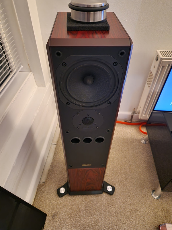
4 vents is a bit weird. The tweeter is quite interesting (i guess it is a superTweeter given what looks like a tweeter at about knee height under the woofer. Note that given the XO of a superTweeter, it should be as close tothe tweeter as possible.
This loudspeaker will be an ML-TL given the aspect ratio of the box, the placement of the woofer, and vents. From the vents placement one would suspect that the designer didn’t know that (where is the one on the back?)
I am not a big fan of foam for damping*, but it does not need to be firmy attached, but it shoulod be sliceable such that it iis friction fit. In an ML-TL damping can range from lining of the walls, to completely filling it will some variety of polyfluff.
*(i like using it foraperiodicm venting.)
How is the bass? What are the internal dimensions? How far from the bottom are the vents? Distance of driver centre from top.
Without the T/S of the driver it is not really possible to simulate it, but someone like Scott (@Scottmoose) can probably offer some inights intothe resonant structure in the box.
One start to specualte how one could rejug all the bits to get better performance.
dave
Audio Tools
You have toget the bit (LARSA?) that does all that. For about $250 USD (hardware + Software) that uses your iPhone/iPad as computer, you need to get a cable to connect the output of the rig to the amplifier to get teh meaurement stimulaus into the system.
The RTA in Audio Tools is sorta OK, i mostly use thde SPL meter.
dave
- Home
- Loudspeakers
- Multi-Way
- ‘Boxy colouration’ or internal reflections through cone