should just the gated measurements be used or should the actual smoothed fr be used when making changes to the crossover? the gated measurements suggest reinstalling the parallel 12 ohm resistor and adding 1 mh to C2 or adding C4 and R3 in and removing C3 all together. the smoothed fr suggests the 12 ohm resistor in parallel should be 20 ohm. the changes do not appear to change the phase or the impedance. Is a flat impedance better? a 20 ohm resistor in parallel with the tweeter before C3 flattens both peaks of the impedance. and keeps it above 4 ohms for the most part.
The gated measurement should be used for crossing, and for dealing with specific speaker design issues. An in room measurement should be used for speaker placement, and for broader speaker design issues regarding room integration. Also, notwithstanding the lower few octaves an in room measurement might be used for broad, gentle EQ such as a simple tone control.
That said, there are often discrepancies left over and a temptation to go to town on the EQ. This is better left on a global level (separate EQ device before the crossover) rather than integrated into the crossover, assuming the crossover has been done properly.
That said, there are often discrepancies left over and a temptation to go to town on the EQ. This is better left on a global level (separate EQ device before the crossover) rather than integrated into the crossover, assuming the crossover has been done properly.
[Disclaimer in case you feel at any time that I cease to make sense. Every point in the circuit has a different impedance. The answer to your question could be different for every point in the circuit.]Is a flat impedance better?
You seem to be asking whether removing the impedance variations that the driver itself naturally has, would be a good thing. If these variations were somehow allowed to impose themselves onto the response, this wouldn't necessarily be helpful because the shape of the impedance does not reflect a desired response EQ. With care, this shouldn't be an issue.
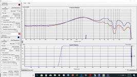
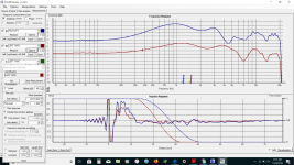
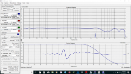
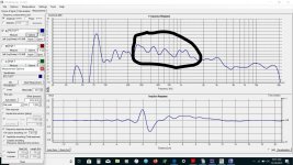
thank you Allen. Attached are two gated FR charts. the blue line shows a flatter response from the gated response to 20k. the red line shows flatter response if the area lower than the gated area is included. Which is the better FR?
sorry for the questions I never really worked with gated measurements before. does the hump at 1k reflect the actual or is it a product of before and after gating? it is not apparent in the smoothed response
sorry for the questions I never really worked with gated measurements before. does the hump at 1k reflect the actual or is it a product of before and after gating? it is not apparent in the smoothed response
Attachments
Last edited:
The 1kHz thing wouldn't necessarily be there if the gate wasn't nearby. I can see you are avoiding the wiggles between 23cm and 47cm and so don't want to set the gate lower. You want to find out whether they are the speaker or room, and either fix it or accept it as a part of your design so you can gate further. [As a side note, hypothetically for a reflection included measurement to be useful in a crossover situation I would think it should be saturated with many and varied reflections.] Sometimes diffraction is easier to work around when taking multiple measurements as it averages in a certain way. However in your case, what's with the dip at 7k5Hz?
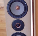
I look again at the photo. I see some opportunity for filling and levelling around the tweeter and woofer edges that are near the tweeter (maybe with putty). Try using absorbing material nearby.
I look again at the photo. I see some opportunity for filling and levelling around the tweeter and woofer edges that are near the tweeter (maybe with putty). Try using absorbing material nearby.
Attachments
Thank you again Allen.
The cabinet is 23cm wide. I don't see anything at 47cm the top of the cab is about 32cm.
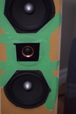
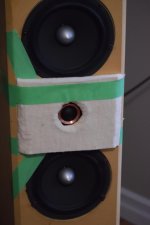
I taped the tweeter and around the woofer using painters tape and then added a felt hood over the tweeter frame here are pics and results.
I have a round hole in the felt for the tweeter I read somewhere that a square hole may be better.
Looks like I will need to build new cabinets or at least a new baffle. My tools are considerably better now as are my skills.
The cabinet is 23cm wide. I don't see anything at 47cm the top of the cab is about 32cm.
I taped the tweeter and around the woofer using painters tape and then added a felt hood over the tweeter frame here are pics and results.
I have a round hole in the felt for the tweeter I read somewhere that a square hole may be better.
Looks like I will need to build new cabinets or at least a new baffle. My tools are considerably better now as are my skills.
Attachments
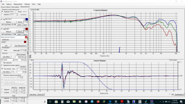
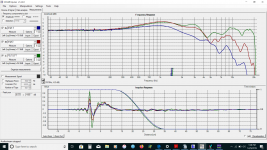
here are the speaker measurements spinning the speaker so on and off axis. I did take a page out of duntech's book and cut stars in the felt. did not make much difference. I am not sure but it looks like the entire tweeter needs to come up? the second chart has angle 3 with is about 70 degrees off I think the moving dip is edge diffraction? but it looks like the depression at 3-6k and the dip at 15 may be speaker/crossover related not sure.
Attachments
Last edited:
What you say about the second chart makes sense. Not sure I agree with you about the 13k dip. Duntech make stars to deal with the felt creating diffraction.
In this context, the dip now seems to make sense. The kind of averaging you want, rather than switching to raw response, is to measure at various angles, gating according to the presence of the room and use a sim that can combine them into a power plot.
In this context, the dip now seems to make sense. The kind of averaging you want, rather than switching to raw response, is to measure at various angles, gating according to the presence of the room and use a sim that can combine them into a power plot.
I used to work with a tweeter that had a rather broad dip and it wasn't anything I could do about it. I left it that way, managed to cross below that normally and it sounded well. The problem is to accept it, especially since manufacturer's data showed nothing like it.
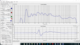
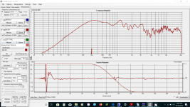
thank you both - this is the best looking gate I can get with moving the gating with the star cut felt in place still an issue around the 6 cm zone. In the raw data and in the gated data generated by holms and in the x sim there is a 3-4db shelf in the 450-1500 range maybe it is not worth worrying over. I will work on putting together a power plot.
Attachments
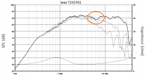
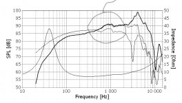
Above and smoothed data the woofer is the 450-1500 shelf here is the tweeter
Attachments
Last edited:
That looks a little like one of those woofers from the time that the trend was to line up all of its design tradeoffs in a row so that you can take it all in with one simple filter, but it only works if you pick the right crossover frequency.
I am not sure what to do I was editing the last message while you were posting. the crossover takes care of the peak pretty well but the shelf in post 153 is the problem I have not been able to figure out how to get rid of that. I could lower the crossover but not to 500hz increasing L1 may work.
Last edited:
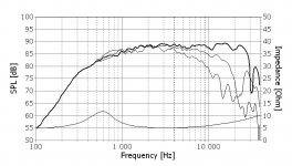
Can you measure down to near 300Hz without reflection? It should be established what the baseline is, ie is that fall below 300Hz due to the room? the peak at 300Hz? etc.
Last edited:
I can try in the morning. I an letting holms determine the gate. maybe moving closer to the speaker? the room is small. 12.2ft x14.6 here is a chart with the star felt where I moved the gate to 300
Attachments
Last edited:
I didn't mean to quote a specific number, although 300 is not unpopular, it's the baseline that is of interest (sorry, that's probably obvious).
I hadn't noticed that it even does that 😛I an letting holms determine the gate.
- Home
- Loudspeakers
- Multi-Way
- Box port or crossover dippity do