Hi Allen.
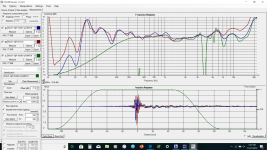
I have been doing some reading even went back and reread your excellent sticky on crossovers without measurements and read a speakermakers journey and spent some time on Lynn Olsens site. The first thing is I know nothing!!!. the next thing is I tried a variety of things in moving the resistors to different positions in the crossover from the first component like in your diagram onto other combinations in xsim. I ended up with the R3 in parallel with C4 instead of in series. The Fr is choppier but the overall direction is flatter and has a very slight downward slope until about 15k. the impedance flattens out little bit and the s3 Wattage peak drops from 1.2w to .6 w.(I am assuming that is what you mean by load) Still have work to do in the dips and the choppy response. I do not seem to be able to find a spot where the dips are removed by moving the gating. I have spent quite a bit of time trying to find a local place to calibrate my spl meter but no one I have talked to has any idea of what I am talking about. thank you again.
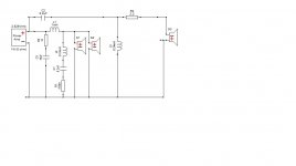
Chart red is with C4 and no resistor blue = raw data with parallel resistor. green is gated with parallel resistor.
I have been doing some reading even went back and reread your excellent sticky on crossovers without measurements and read a speakermakers journey and spent some time on Lynn Olsens site. The first thing is I know nothing!!!. the next thing is I tried a variety of things in moving the resistors to different positions in the crossover from the first component like in your diagram onto other combinations in xsim. I ended up with the R3 in parallel with C4 instead of in series. The Fr is choppier but the overall direction is flatter and has a very slight downward slope until about 15k. the impedance flattens out little bit and the s3 Wattage peak drops from 1.2w to .6 w.(I am assuming that is what you mean by load) Still have work to do in the dips and the choppy response. I do not seem to be able to find a spot where the dips are removed by moving the gating. I have spent quite a bit of time trying to find a local place to calibrate my spl meter but no one I have talked to has any idea of what I am talking about. thank you again.
Chart red is with C4 and no resistor blue = raw data with parallel resistor. green is gated with parallel resistor.
Attachments
Are you comparing with REW, as these were imported?
'Load' refers to the impedance that a given part of the circuit is seeing.
Many audio amps are Voltage sources, which means they have a problem with being shorted. When you run a capacitor across the terminals you should see that there is sufficient impedance behind it (in series) at higher frequencies to prevent the amp seeing a short circuit. For example, a low pass filter has an inductor in series before the capacitor to ground. In this case though, you are safe.
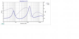
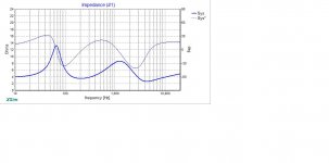
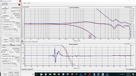
hello Allen here are the impedance graphs with and without the resistor.
I am still using REW and I do not trust the microphone so I think measurements from here on may be of less value. I read quite a bit about the radio shack spl meter and it may not be trustworthy. I tried the measurement with and without the recommended calibration file and the difference is over 6 db at the high frequencies. without measurements I am not really sure how to proceed. just listen I guess. I will continue to look for a mic there is a Dayton emm 6 in the swap meet but I am not sure if that is a correct mic to use or not.
thank you again for all of your help Allen
Attachments


Think about getting usb mic that has everything it needs within, unlike emm-6. Separate phantom power, probably pre-amp or not, and a sound card.
Excellent idea. Has there been a consensus as to whether a USB mic will function with Holm and its single input channel with regard to timing? Although it seems it should I recall reading something to the contrary.
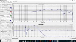
Allen how important is the flatter impedance if I add a parallel resistor and cap to the woofer pair like in your sticky the impedance flattens and I can use components already in the cross by dramatically reducing the components in the tweeter it looks like the FR stays close to the same.
Attachments
Hey 8, Lojzek's suggestion is interesting. I've been considering it myself.
Impedance conjugation is typically used in two places with speakers, to flatten the load for the filters and to flatten the load for the amp. If you want to do both you have to do it twice.
The reason I say this is because we have been talking about both at different times and I want to get it straight.
Doing it like in the sticky, is not always done when measuring because it isn't mandatory for good control over the response result. It is often helpful in a tweaking situation like you find yourself in now. I do it with my tweeter impedance as it has a difficult nature and does not lend itself easily to being worked around. Otherwise, I don't typically do it.
Thank you Allen and Lojzek. Not trusting the measurement I feel like I have wasted your time. I did not realize the SPL meter was that inaccurate. I will try to purchase one of the usb mics. thank you both. I have to say that the overall sound of the speakers is quite good. but I am quite certain they are still not at their potential.
I found a tech to look at the Primare.
I have found a lot of differing opinions on the net so I am going to ask. Is a simpler crossover better? Reducing the tweeter crossover to 1 cap 1 coil and 1 resistor keeps about the same FR but lowers the impedance peak from 19 to 8. An impedance flattening stage would have to be added to the woofer. so the woofer gets an extra cap and resistor. I think the Nextel drivers may be quite a bit easier to manage in the break up region than the metal drivers were. I think some of those components on the tweeter side were to help with the sound of the metal driver breakup. Or should I just leave well enough alone until I get a calibrated microphone?
thanks again
Ben
Last edited:
A middle of the road complexity crossover solution is by far the closest to the optimal if we were to analyze an average hi-fi commercial loudspeaker. The simplest I would approve as a succesful design would be a single LP inductor, and a 2nd order electrical with a padding resistor for the tweeter HP. This assumes a well behaved woofer cone as paper and polypropylene usually are. Obviously woofer metal cones need further attention in form of network circuits to shape their response whenever employed near break-up region. Further complexity to the circuit could be in shaping the impedance, either to make an amplifier see an easier load and/or to improve spl summation of woofers in the bass region where larger impedance peaks usually exist.
Last edited:
thank you Lojzek and Allen
I am wondering if a simplified crossover would sound better even thou the speakers sound good this crossover was designed for the metal and less efficient woofers. I found the mic at solens so I will buy on Monday with a few different size resistors.
I am wondering if a simplified crossover would sound better even thou the speakers sound good this crossover was designed for the metal and less efficient woofers. I found the mic at solens so I will buy on Monday with a few different size resistors.
So not really simplifying, just rearranging? Your crossover has a job to do. It may be doing more than is obvious such as taking out the woofer breakup region. Such comparisons should be made under better controlled circumstances.Reducing the tweeter crossover ..... An impedance flattening stage would have to be added
Thanks Allen, As I am reading more and more I get ideas and like they say a little knowledge is a dangerous thing. I am just going to get the microphone and measure and go from there. I just saw a way to take 2 caps and a resistor out of the tweeter crossover and flatten the impedance. But like I read somewhere xsim is not a video game.
I once came to the same feeling.. However crossover hacking can lead to strange and unpredictable results with a more complex circuit, leading to a half-baked conclusion.
I think you are correct Allen. I imagine Joe, the guy who designed the Thor crossover, would know a little more about D' Appolito crossovers than I do.🙂. I think getting the mic is a good idea. I really do not know where I am without it.
Crazy but our Canada Post man showed up today SUNDAY and dropped off the microphone. Here are the first readings directly to holms with right and left speakers at 1 meter gated just the way holms recorded it. Not sure about the phase I have read about it but I have been having trouble comprehending it. it looks like the phase changes 180 degrees at the crossover would that not mean a poor crossover cohesion?
Attachments
Last edited:
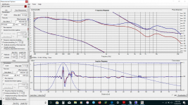
No, it just means your tweeter is rolling off.it looks like the phase changes 180 degrees at the crossover would that not mean a poor crossover cohesion?
- Home
- Loudspeakers
- Multi-Way
- Box port or crossover dippity do