I found some nice 24 position stepped attenuators in a surplus store for my BoSoZ to be built soon.
My questions:
1) Which kind of attenuator is the most suitable
to replace either P1-P2 and P3-P4? I mean a
simple series attenuator or a shunt or ladder type? I am asking this because it is difficult
to assemble a 5K series attenuator with the
resistors avalaible to me; it would be much easier to build a shunt attenuator. I was wondering
if P3-P4 could work in shunt mode.
2) Which is the correct range of attenuation both
for the input and output, e.g. 40 or 60 dB?
I used stepped attenuators in shunt mode as a substitute for P3/P4 in my BoSoZ preamp and they worked fine. For this shunt make sure that the switch is a shorting (make before break) switch, if not your volume will spike between settings.
I good place for your master volume is P5, which adjusts the gain. In my preamp, I have 5dB steps.
In my preamp, I use 2, 4-deck stepped attenuators for P1/P2 in a ladder mode. Each channel had its own 4-deck switch, which allowed balance control as well as fine volume control (I have 1dB steps).
If I were to do it again, I would:
* eliminate the P1/P2 ladders
* have separate P3/P4 switches in shunt mode, with each channel having its own 2-deck switch, which allowed balance control as well as fine volume control (I have 1dB steps)
* use a 2-deck discrete switch for P5 for the master volume in 5dB steps
Stepped Attenuators Explained
I thought this is a good link for explaining all the different type of stepped attenuators. http://www.goldpt.com/info.html
I thought this is a good link for explaining all the different type of stepped attenuators. http://www.goldpt.com/info.html
In this article
http://www.audioxpress.com/reviews/media/AE398CF.pdf
the author made a 2K stepped attenuator using 22R6 as the lowest.
I am building the Bosoz also, and would like to make a 5K 24x2 attenuator for my P4 (as the only volume control), but I can't figure out the resistor values for 5K...so maybe I go for a 10K as P4.
Custom resistance value for Balanced Stepped Attenuators
http://www.marchandelec.com/att.htm
The above link sells a 5K, 24 position balanced stepped attenuator kit for $200. Assembled is $300. Model # is AT24-4-"substitude your resistance value here". They can do any resistance value.
And for 46 position, it's $500 kit, $900 assembled. Model # AR46-4-K.
I obtained the above information from Phil Marchand at Marchand Electronics.
At the output of BOZ or BSOZ, either shunt or ladder
will work fine.
At the inputs, a ladder is preferred.
will work fine.
At the inputs, a ladder is preferred.
I am sure this might help someone about figuiring customs value for a stepped attenuator.
http://quadesl.com/attenuator.html
😎
http://quadesl.com/attenuator.html
😎
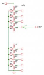
I believe that estimating resistor values for a shunt attenuator is basic freshmen level physics, just calculate the voltage drop divide between the series resistor and the load resistor and
dB = 20* log(V1/V0).
It is good to create an Excel spreadsheet to do the math and allow you to substitute actual resistor values (I did this, but saddly a harddrive crash wiped out my file).
Here are the values that I used for a 12 step switch for shunt in place of P3/P4 (assuming R9/R10 series resistors of 221 ohm and R11/R12 load resistor of 100K ohm in parallel with the shunt):
0.47 ohm -53.5dB
0.75 -49.4
1.3 -44.7
2.4 -39.4
4.3 -34.4
7.5 -29.7
13.3 -24.9
24.9 -19.9
49.9 -14.7
105 - 9.8
287 - 5.0
Open 0.0
Also found this calculator
http://homepages.tcp.co.uk/~nroberts/atten.html
From this site I downloaded another excel spreadsheet for calculation:
http://www.siteswithstyle.com/VoltSecond/12_posistion_shunt/12_Position_Pure_Shunt.html
http://homepages.tcp.co.uk/~nroberts/atten.html
From this site I downloaded another excel spreadsheet for calculation:
http://www.siteswithstyle.com/VoltSecond/12_posistion_shunt/12_Position_Pure_Shunt.html
I have some further questions:
1. How do I know if the normal 1% metal films I buy at the local shop for my attenuator are "matching resistors"? And should I use 0,1% resistors instead?
2. On my existing preamp I sometimes use the balance control to adjust left-right. Thus I would like to place a balance control in my BosoZ before the P4 attenuator. I don't want to use two volumen controls, one for each channel, so I figure this circuit figure 5 may be used:
http://sound.westhost.com/project01.htm
This guy recommends that BAL = 2,5 x VOL, so for my 5K volume it will be 12,5 K.
Is it possible to use a high quality attenuator as volume and a cheaper (linear) pot as balance, or should they be the same parts?
What are the drawbacks with a balance control apart from longer wiring?
Thanks.
Easiest way to get matching resistors is to buy 10 for every 2 you need then match them with a digital multimeter. 1/4W 1% are cheap enough that it's an affordable process.
Standard Pot = Series Pot
<a href="http://www.siteswithstyle.com/VoltSecond/12_posistion_shunt/12_Position_Pure_Shunt.html"><img src="http://www.siteswithstyle.com/VoltSecond/12_posistion_shunt/SHUNT_MODE_POT_CONFIG_B.gif" >
</a>
Theres also constant impedance <a href="http://www.geocities.co.jp/Technopolis/5053/amp/t_att.htm"><img src="http://www.geocities.co.jp/Technopolis/5053/amp/20kATT.gif"></a>
Pics are links
James
one resistor in signal path?
(thank you, James)
Am right that , depending on which attenuator you use there is onl oen resistor in signal-path, the switched second resistor goes to ground
That means that i only need to use very high quality resistors for those in signal path and for the others i could use cheper ones without loosing sound quality?
regards,
Ralf
Hi,
Ordered the Balanced Line Stage and p/s boards (PCB Design) While studying previous post's on the attenuator subject I was stopped dead in my tracks. Up to here it all looked fairly simple.
When I read Nelson's post below I am confused.
I somewhat understand the shunt and ladder types. Is he suggesting a 4 gang pot with 2 used for the input side and 2 for the output? (I do not see how that would even work.) Question is are we using a 5K 4 gang ladder type or ? I will use balanced inputs and outputs with RCA's wired in parallel as described in his text. My speakers are 2-way 95db and 8ohms.
While most power amps are easy for me preamps are not. I always end up with too much volume or not enough and usually have a hum (tube design) problem to be worked out.
Thanks,
Brad
Ordered the Balanced Line Stage and p/s boards (PCB Design) While studying previous post's on the attenuator subject I was stopped dead in my tracks. Up to here it all looked fairly simple.
When I read Nelson's post below I am confused.
Nelson Pass said:At the output of BOZ or BSOZ, either shunt or ladder
will work fine.
At the inputs, a ladder is preferred.
I somewhat understand the shunt and ladder types. Is he suggesting a 4 gang pot with 2 used for the input side and 2 for the output? (I do not see how that would even work.) Question is are we using a 5K 4 gang ladder type or ? I will use balanced inputs and outputs with RCA's wired in parallel as described in his text. My speakers are 2-way 95db and 8ohms.
While most power amps are easy for me preamps are not. I always end up with too much volume or not enough and usually have a hum (tube design) problem to be worked out.
Thanks,
Brad
Seems like an awful lot of resistors and joints in the signal path. Previous one looks better (Ralf).
/UrSv
/UrSv
i have just ordered DACT CT2-10K-4 for the revision of my BZLS. I have been pondering with this problem for a while, and found that there is no free lunch. The resulting 2,5K output Z halves the HF rolloff point, but I wouln't loose any sleep over it 🙂
BTW, it is nearly finished, so there will be some interesting pics soon, as I have made it in a rather unusual way
BTW, it is nearly finished, so there will be some interesting pics soon, as I have made it in a rather unusual way

- Status
- Not open for further replies.
- Home
- Amplifiers
- Pass Labs
- BoSoZ stepped attenuator