UrSv
I think You are right.
Ralf
When the whiper is in contact with two poles, the You will parallel a pair of resistors, this means more attenuation in this position. In other words, if You slowly turn the knob, do You hear any irregularity in the natural increasing or decreasing of the volume?
If not, I will tend to change the resistors on my Elma swiches.
Brad Kizer said:I somewhat understand the shunt and ladder types. Is he suggesting a 4 gang pot with 2 used for the input side and 2 for the output?
Ideally, the balanced line stage is operated balanced in and
balanced out. If this is what you are doing, logically you can
place 2 input pots on each channel, or 2 output pots, or both.
Because you can otherwise overload the inputs with a high
enough signal, input pots are advisable, but the best way is
to have both input and output pots. I set them up separately,
so that input and output are adjusted independently, and
I adjust the input level for the loudest level I will want with
the output pot up all the way. Then I use the output pot for
day-to-day volume control.
Doing it this way allows for a 4 pole input ladder pot (a shunt
might load the source too much) and a 4 pole output ladder or
shunt (BOSOZ doesn't care) for two channels.
Yeah, it seems like a lot, but it does give best results.
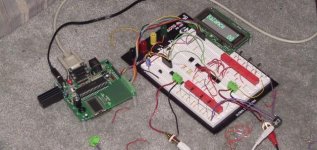
It seems like there is a lot of ways to run the volume control with the BOSOZ. I currently have a relay based balanced volume control, controlled with a microcontroller, like the one from the P1.7, shown in the pic below.
I was planning on just using this for the output of the BOSOZ. Will this work well enough, or should I also put one in P5, or at the input? I am planning on just using a single ended input and a balanced output into an Aleph.
--
Brian
I was planning on just using this for the output of the BOSOZ. Will this work well enough, or should I also put one in P5, or at the input? I am planning on just using a single ended input and a balanced output into an Aleph.
--
Brian
Attachments
Many thanks to all!
Mr. Pass you nailed it! Didn't think about it until you replied. Then I remembered my guitar's volume control and those (master and pre)on the amp. Same idea..control the input and output. Makes perfect sense to me now.
The "best results" are paramount. Would you use, four 5K poles or a pair of 10K and 5K poles or ? I'm looking at using your Zen V4 if that helps in your recommendation. Goldpoint has a ladder kit minus resistors that would work nicely.
Thanks,
Brad Kizer
Nelson Pass said:
Because you can otherwise overload the inputs with a high
enough signal, input pots are advisable, but the best way is
to have both input and output pots. I set them up separately,
so that input and output are adjusted independently, and
I adjust the input level for the loudest level I will want with
the output pot up all the way. Then I use the output pot for
day-to-day volume control.
Yeah, it seems like a lot, but it does give best results.
Mr. Pass you nailed it! Didn't think about it until you replied. Then I remembered my guitar's volume control and those (master and pre)on the amp. Same idea..control the input and output. Makes perfect sense to me now.
The "best results" are paramount. Would you use, four 5K poles or a pair of 10K and 5K poles or ? I'm looking at using your Zen V4 if that helps in your recommendation. Goldpoint has a ladder kit minus resistors that would work nicely.
Thanks,
Brad Kizer
It seems to me that the input level control could be a more coarse control like with maybe 6 steps with discrete resistors. which would be cheaper to implement. Then use the your expensive multi step control (or pot) on the output.
Brian GT- when are you making a circuit board for a relay/microcontroller control. I guess each board could have a pair. Since I'm dreaming, include a programmed controller
Brian GT- when are you making a circuit board for a relay/microcontroller control. I guess each board could have a pair. Since I'm dreaming, include a programmed controller
Variac said:It seems to me that the input level control could be a more coarse control like with maybe 6 steps with discrete resistors. which would be cheaper to implement. Then use the your expensive multi step control (or pot) on the output.
Brian GT- when are you making a circuit board for a relay/microcontroller control. I guess each board could have a pair. Since I'm dreaming, include a programmed controller
Actually, I am making a pcb for myself for the volume control when it is finished being prototyped. By using 8 relays per channel (balanced signal), it gives you 256 steps of precision. My roommate is actually doing all the work for the project and getting credit for it in school this semester. He also made a pga2310 based volume control earlier this semester, and is finishing up the relay based one now (it is due in 2 days to demo to his professor). Once he wraps it up, my plan was to make a pcb for it with 16 relays, 8 for each channel, a PIC microcontroller and the necessary voltage regulation chips. This should be a good passive preamp. I like that you can really easily change the value of it by swapping out the 8 resistors per channel (or 16 if using it balanced).
Once I get a version finished with a pcb, it might be fun to get a bulk pcb order together and I could program the code on PICs for people. I am slowly learning to use microcontrollers myself, and am taking a class in it next semester.
--
Brian
do it do it do it. I'm on board for at least 2 channels. Tell your roomie to stop watching so much TV and help us out!
Brad Kizer said:
"Would you use, four 5K poles or a pair of 10K and 5K poles or ?"
The answer was right in front of me, Just didn't read far enough down the page...
Thanks to all,
Brad
Variac said:do it do it do it. I'm on board for at least 2 channels. Tell your roomie to stop watching so much TV and help us out!
My roommate finished the first prototype. It has 4 DPDT relays per channel, easily allowing balanced use later. The remote control can be used to change the volume and the balance. It should have 8 relays per channel, but no room on the protoboard. It works quite nicely, and much, much, much cleaner then the pga2310 setup. I like it.
--
Brian
Attachments
moved picture, and put up a gallery from this project:
http://brian.darg.net/relay
I like the tactile click when you change the volume 🙂
--
Brian
http://brian.darg.net/relay
I like the tactile click when you change the volume 🙂
--
Brian
Brian ... very nice. I saw the pictures and I guess your roommate is going to get through college without ever sitting on a proper table and chair. Sorry, I just can't resist.
fcel said:Brian ... very nice. I saw the pictures and I guess your roommate is going to get through college without ever sitting on a proper table and chair. Sorry, I just can't resist.
He has a nice leather office chair and desk in his room, he just likes to sit on the floor and chair in the living room... I keep on telling him that it is bad for his back. I think that the root of the problem lies that there is no television in his room. I am going to pick him up one from home over the break and see if this solves the problem 🙂
The next step is a pcb. It shouldn't be that difficult.
--
Brian
Hi Brian,
very nice.
I definately would be interested in the project and also the PCB's when ready!
Best regards, also to your roommate!
Martin
very nice.
I definately would be interested in the project and also the PCB's when ready!
Best regards, also to your roommate!
Martin
martinschki said:Hi Brian,
very nice.
I definately would be interested in the project and also the PCB's when ready!
Best regards, also to your roommate!
Martin
Thanks, I will work with my roommate to get this design matured into a pcb form, then we can see about doing a group project with this. One issue would be the remote control. Currently, he just picked the sony remote control, as it is a commonly used remote control, but it conflicts with my television also... There are quite a few plans for remote controls, so we might end up just making our own remote control also. I am thinking of changing it to using an rca remote control, as they are quite cheap ($10 for the small one in stores).
--
Brian
Brian,
What development board is your roommate using to program the PIC microcontrollers? Microchip's PICStart Plus at $99 is a bit more than I'm willing to spend to just program a serial bootloader onto the PIC chips.
Also, what's the model of that LCD screen on the breadboard and where can I get one? It looks like it'd be a great display for a preamp.
Thanks,
Greg
Possum said:Brian,
What development board is your roommate using to program the PIC microcontrollers? Microchip's PICStart Plus at $99 is a bit more than I'm willing to spend to just program a serial bootloader onto the PIC chips.
Also, what's the model of that LCD screen on the breadboard and where can I get one? It looks like it'd be a great display for a preamp.
Thanks,
Greg
The board that is use was developed for a class at my school. Here is the teacher's website: http://www.picbook.com I bought the pcb for $10 (the board also is included with the book), and then you can order the parts kit from digikey: 18F452-KIT It costs $56.94 and includes a whole lot of things for development:
The 18F452 has a built in ADC, and there is a DAC on the board, RPG (rotary pulse generator, which is a cheap version of an optical decodes), pot, temperature sensor and easy outputs to tie to external devices serially, such as vfds and stuff. He also gives a good deal of sample code. If you buy his book (links on the above website, you can find it for a little over $50:
http://www.addall.com/New/submitNew...pe=ISBN&location=10000&state=AK&dispCurr=USD
For a little over $100, you can have a good reference book, and a great development board. For the board for easy development, it uses a program called Quikbug that gets programmed to the pic, then it allows you to connect over a serial connection with terminal software, then you can drag and drop files to upload, set breakpoints, step by step through your code, and debug. Pretty soon, they will have an editor written for this board that will allow you to upload your code to the board with the click of one button. It is the focus of a class at Georgia Tech. I am taking the class next semester, and my roommate took it last semester, and this semester worked with the professor, and made the volume control for his final project.
As for the VFD, I bought it directly from Noritake:
http://www.noritake-elec.com/7000.htm
It is absolutely beautiful. It was expensive: just under $100 shipped. It is 140x32 pixels, and the part number is: GU140x32F-7002
Here is another shot of the vfd from my roommates other semester project:
--
Brian
Attachments

Brian,
I was thinking of ordering the $140 "41 steps attenuator" (from the other thread) for my BOSOZ. Is what you're designing serves the same purposes but it's a electronic volume controller? How much ... rough estimate and how easy is it to build?
I was thinking of ordering the $140 "41 steps attenuator" (from the other thread) for my BOSOZ. Is what you're designing serves the same purposes but it's a electronic volume controller? How much ... rough estimate and how easy is it to build?
question:
If I was to finish the pcb for this, and make a 2 channel volume control for 2 balanced channels with 8 relays per channel, remote control use, ability to set balance, option for display, rpg for also changing volume, would anyone be interested in a group order of these? To get pcbs made, I need to get some group interest to get the price lower. I calculated that if we can get a total of 30 boards made, I could have all of the parts for the boards, and even assemble and test them for about $100 per two channel setup. Would anyone be interested in this? I thought first about just supplying the boards, but relays are much cheaper in quantity, and so are the microcontrollers. Also, it would be good for me to personally test each one before shipping it out. All that would need to be done by the person who gets the boards would be to pick the resistors (16 for unbalanced and 32 for balanced, 8 per channel). This would give 256 steps of precision for the volume.
If there is enough interest, I will get a group order together, and do this. I figure that for $100 per board with all parts included, it can be quite robust. Even a cheap lcd display could be included with this, with the option to plug in a vfd like mine. If a lot of interest is generated with this, the price could go down a whole bunch, due to cheaper vfds, cheaper microcontrollers, relays, etc.
I will make a more detailed thread about this, after the pcb design is worked out for myself. If there isn't enough interest, I will just get a couple of boards made for myself here at school.
--
Brian
fcel said:Brian,
I was thinking of ordering the $140 "41 steps attenuator" (from the other thread) for my BOSOZ. Is what you're designing serves the same purposes but it's a electronic volume controller? How much ... rough estimate and how easy is it to build?
Which thread are you talking about?
If I put together a pcb and package a kit, it will be quite easy. I could sell it either unassembled or assembled for a bit more. The volume control is totally passive, the signal going just through the 8 resistors and the 8 relays.
My roommate and I are designing this to be a robust remote controlled passive volume control. It is basically a project that we will both be using for our amplifiers, and he has quite a high level of knowledge with the microcontroller stuff now.
My roommate is planning on making a universal learning remote receiver unit for it, so that any remote control will work for it also.
I am hoping to have a fully done prototype on a pcb by the end of january, planning on finishing the pcb design over the break.
--
Brian
- Status
- Not open for further replies.
- Home
- Amplifiers
- Pass Labs
- BoSoZ stepped attenuator