So a few weeks ago I decided to build the SB18 which is more budget friendly. I don't have the time yet, I am curious about the results! R.
You will find a few diy designs using the SB17NRXC35-8 and SB29RDC-4 tweeter. Some are optimized for flat baffle cabinets of various internal volume and bass port tuning. Some crossovers are optimized for a time-stepped baffle. Some crossovers are optimized for a slanted baffle used to create a triangular T-M time alignment at the listener. In the USA designs which fit a common ready-built cabinet from Parts Express are popular.
Lower cost SB26STAC tweeter:
SB Acoustics :: Eka Kit
Attachments
Thanks for your suggestions. I see a lot of different designs with the SB17NRXC35-8. The EKA ket looks very good. Today a pair of SB26STAC came up for sale for half the price... and hope to get them..
Thanks for your suggestions. I see a lot of different designs with the SB17NRXC35-8. The EKA ket looks very good. Today a pair of SB26STAC came up for sale for half the price... and hope to get them..
I have scored them (SB26STAC), while I was searching for a pair of SB17NRXC35-8 I came across a pair of satori mw16p-8 but I don't if they pair up...
R.
Hello there,
I'm having a few challenges reconciling my crossover design. I'm using Linesource's posts above to check my calcs.
The 3rd order Butterworth calculations I do using the cookbook formulas and online calculators result in series lower inductor values in the low pass than both the above designs.
BW3 Crossover fx (Hz) Tweet R ohm Woof R ohm
1700 6 8
C1 10.40uH
C2 31.21uH
C3 15.60uH
L1 0.42 mH
L2 1.12 mH
L3 0.37 mH
Is baffle edge correction significantly increasing series inductor sizes in the two designs posted by Linesource above?
Also, I get different L-pad resistance results. I calculate similar parallel resistor values but lower series resistance values...
eg for 3dB attenuation of my 6 ohm tweeter I calculate 1.8 ohms series R, 14.5 ohms //R. What am I not taking into account?
are you using actual impedance values, or nominal?
Online calculators are OK, but they need a bit of knowledge to get good results
Online calculators are OK, but they need a bit of knowledge to get good results
Nominal Pete. 6ohm tweeter, 8ohm woofer. The online calculators give me the same results as the loudspeaker cookbook formulas. I wanted to understand Linesources design from post #11 better. Especially the L-pad and the baffle edge correction.
Last edited:
Hi Xerxes75. Slowly�� I’ve been busy at work and at home. I’m also stuck on the crossover. Particularly the low pass. There are a couple of designs above for the SB17 that don’t reconcile with my simple calcs and understanding and I don’t want to throw money into buying and trying lots of inductors and capacitors.
I haven't checked your specific case, but this should be because crossover calculators omit the baffle step effect. If you build a LP filter using simply a textbook crossover you'll end up with tiny bass, as this will be 6dB down from midrange/high. Baffle step correction is usually performed with "oversized" coils.I'm having a few challenges reconciling my crossover design. I'm using Linesource's posts above to check my calcs.
The 3rd order Butterworth calculations I do using the cookbook formulas and online calculators result in series lower inductor values in the low pass than both the above designs.
Again, this is a side effect of a baffle step compensation. You have to pad down the tweeter more than you expected, up to 6dB more.Also, I get different L-pad resistance results. I calculate similar parallel resistor values but lower series resistance values...
eg for 3dB attenuation of my 6 ohm tweeter I calculate 1.8 ohms series R, 14.5 ohms //R. What am I not taking into account?
Ralf
Thanks giralfino. Yes, the baffle step correction is where I seem to becoming unstuck. It's tempting to go with Linesources design on page 2 (post #11) which appears to cover it all but I like to understand stuff a bit before I buy🙂 It would be excellent to understand that design better.
Last week I also went through AllenB's tutorial sticky: Introduction to designing crossovers without measurement
It's a simpler approach with lower parts count (2nd order?) but doesn't appear to end up with the oversized coil, baffle step correction that sounds like a good thing to have.
Last week I also went through AllenB's tutorial sticky: Introduction to designing crossovers without measurement
It's a simpler approach with lower parts count (2nd order?) but doesn't appear to end up with the oversized coil, baffle step correction that sounds like a good thing to have.
Since you read the sticky thread, be sure to read also the post #20, or better follow the link from there to the presentation from Dave Dal Farra. AllenB tutorial is good in explaining what happens, but it omits the fact that many have a very powerful system (the PC) that can easily simulate what happens when a driver is put on a baffle. With the same approach you can test the Linesource crossover.
Ralf
Ralf
Hello again. I've looked into this some more and time is getting the better of me🙂 I need some help.
Could one of you fine people help me with the crossover design?
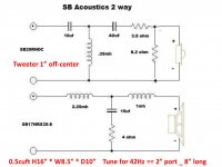
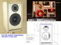
I will make this 18.5L, 38Hz slot ported enclosure:
SB 18 - April 2012 - Loudspeakermagazine 2012 | Loudspeakerbuilding
This crossover designed by Linesource looks excellent but I notice he's allowing for a slightly different enclosure (0.75cuft, 42Hz). Can I use this crossover design or does in need to be tweaked a bit for the 18.5L, 38Hz enclosure linked above?
Could one of you fine people help me with the crossover design?
I will make this 18.5L, 38Hz slot ported enclosure:
SB 18 - April 2012 - Loudspeakermagazine 2012 | Loudspeakerbuilding
This crossover designed by Linesource looks excellent but I notice he's allowing for a slightly different enclosure (0.75cuft, 42Hz). Can I use this crossover design or does in need to be tweaked a bit for the 18.5L, 38Hz enclosure linked above?
Attachments

Hi Xerxes75. I’m using a different (Vifa DG25) tweeter. And I still don’t know how to find all the values..
Last edited:
Hi Roo2, you're right. I mixed up the SB EKA with the SB18. For the EKA you can find the values and even in my best German I can't find the values for the SB18 crossover. But I did find many building threads and numerous shops who provide the crossover parts for reasonable prices although I don't what the shipping costs would be..
R.
R.
Hello again,
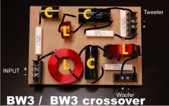
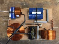
See photo attached. Seeking your feedback on the preliminary component placement for my BW3 crossover before I solder it together. Positive input on left. Both positive outputs on right. High pass across the top. Low pass across the bottom. A common negative ground rail for everything in the centre.
The main bit I'm not sure about is how close I have my first HP capacitor and inductor in the top left corner. I was thinking about moving them apart but that might compromise the position of the inductor wrt the first big inductor in the LP below. Maybe it doesn't matter? What do you think?
Anything else wrong that you see?
Thanks
Attachments
Last edited:
- Status
- Not open for further replies.
- Home
- Loudspeakers
- Multi-Way
- Bookshelf Suggestions