Andrew, in the assembly instructions, there is an order of part placement. I noticed that there is only one reference to U1 and that's while debugging. Is it installed with the other ICs or earlier?
Javier, you can install U1 with the other components. It’s best to put all the passive SMD’s down on both sides of the board, and then all the IC’s. U1 is the zero offset servo for the MC amplifier.
Ok, thank you Andrew. As you can tell, it's my first deep foray into building boards with SMD components. Learning quickly.
I'm moving along okay getting capacitors populated but didn't realize I had some ceramic caps meant for another project, which also happen to be 47 nF. I noticed I didn't have the correct amount and realized my mistake, including the fact that I had placed 1206 chips, not 0805s. Mad scramble to check vs. the BOM and I believe I'm okay because I placed 6 of them and they were C0G types rated at 50V and 1%. Specified parts were 2% at 25V. Time to pause and audit what parts I have before I end up with a rework job on my hands.
Andrew, yes, I read your post on use of X7R vs. C0G (now stored away in my permanent memory banks) and when I discovered my error, that was the first thing I checked on the Mouser bag. 😀 What a relief to not have to remove them.
Marching forward towards audio happiness!
Marching forward towards audio happiness!
Here’s the link to the video on soldering SMD components
How to place and solder SMD components - YouTube
How to place and solder SMD components - YouTube
Andrew, what was your tip temp in the video? I'm using 260 on mine but compared to your video, my solder seems a tad slower to go liquid. BTW, I kept expecting your faithful pup (Alfie?) to show up and give a helping paw. 🙂

Hello folks,
Could you please help me confirm which component values to go by?
I finally got (almost) all the parts on the BOM together and am getting ready to start populating my board but want to make sure that I’m placing the correct components. I’m seeing resistor values printed on the board that don’t match the BOM. I know that a while ago (post #71) the word was to go with the values in the BOM, but I just want to make sure that I’ve got this right. I’m looking at a BOM version that says April 2020 at the top so I think that it’s the latest.
So, for instance R1 and R2 have printed labels of 68k, but I should use 47Ω because that’s what’s on the BOM. And similarly R11 and R12 are labeled 47k, but I should use 47Ω, etc.
Thanks for the help.
U1- on schematic
U1 is listed as OPA2188 on the schematic and on the board. In the BOM its listed as OPA2189, which is what I have used. What should I have used? Also a bit of guidance, should we follow the schematic, the board or the BOM?
Regards , Ashley
U1 is listed as OPA2188 on the schematic and on the board. In the BOM its listed as OPA2189, which is what I have used. What should I have used? Also a bit of guidance, should we follow the schematic, the board or the BOM?
Regards , Ashley
Ashley,
Both will work. I used OPA2188 on both my builds.
The schematic and the PCB values are all correct. I will update the BOM later this week - just been blind busy the last few weeks.
Both will work. I used OPA2188 on both my builds.
The schematic and the PCB values are all correct. I will update the BOM later this week - just been blind busy the last few weeks.
audioXPress have very kindly agreed to make both Part 1 and Part 2 articles available to download in pdf format towards the end of next week and for me to provide updated BOM information on tne supplementary download information. This should make the preamp more accessible to a wider range of builders.
So, should I be going by the labels on the PCB for component placement rather than the BOM?
I just went through and compared the (latest on Bonsai's website) BOM and the PCB and the component numbers for the capacitors anyways are almost all different. I'm guessing that the PCB value labels are correct because the labels match the footprints of electrolytics, but it would be nice to know for sure.
For example the capacitor labels on the PCB are:
1uF 805 : C1, C2, C38, C39, C57, C58, C59, C60, C76, C89, C91, C93, C94 (2x unlabeled on bottom of PCB)
1000uF 10V : C11, C16, C17, C18, C19, C20, C21, C23, C30, C77, C88
2.2uF FLM : C8,C9,C22,C25
22uF 35V : C12,C13,C14,C15,C62,C79
47nF 1% : C16,C94
12nF 1% : C17,C23,C24,C32,C51,C93
820pF 5% : C18,C92
220pF : C21,C26
220uF 6.3V : C33,C34,C43,C44,C49,C50
3.3nF : C36,C45,C61,C69,C80,C85,C86,C87
100uF 25V : C46,C47,C63,C64,C65,C66,C73,C74
47nF 2% : C53,C54,C57,C58,C59,C60,C67,C68,C81,C82,C83,C84,C90,C91
0.1uF 50V : C70,C77
2200uF 35V : C71,C72
0.1uF 275VAC X2 : C78
I haven't reviewed all the resistors but it seems like similarly the count on the BOM is mostly right but the component numbering is off for most resistors.
I will look at this tonight. The BOM vs the PCB s the schematic is tight except for 3 or 4 components. The PCB and Schematic are all correct.
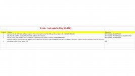
Here is the Errata sheet that covers the BOM and the orientation of C9 and C25.
The AX supplementary data will be updated later today as well.
Please carefully read the assembly instructions because it explains how to mound the film capacitors underneath the PCB
The AX supplementary data will be updated later today as well.
Please carefully read the assembly instructions because it explains how to mound the film capacitors underneath the PCB
Attachments
- Home
- Source & Line
- Analogue Source
- Bonsai’s X-Altra MC/MM Phono Preamp