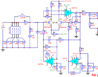
Synthetic Load schematic
Rick
Not I, since it is copyright info from Elektor and Doug Self. You can purchase the article from Elektor, it was in May 2012.... and probably you would not show us the details, like the schematic?
Rick
... and probably you would not show us the details, like the schematic?😉
Bob's post just above yours gives it all away...
jan
... and probably you would not show us the details, like the schematic?😉
Hi Pawel,
Are you referring to the phono circuit from the early 1980's that I mentioned above?
Cheers,
Bob
Hi Bob
I do not want to be intrusive
I just wanted to know your practical circuit of synthetic mm cartridge loading
but of course I understood that it was not a part of your great article in LAv4
I do not want to be intrusive
I just wanted to know your practical circuit of synthetic mm cartridge loading
but of course I understood that it was not a part of your great article in LAv4
Doug Self implemented the synthetic cartridge load ckt in the new 2012 pre-amp that was published in Elektor, have a look at that!!
Rick
It has been used since 1980-ties, AFAIK.
An externally hosted image should be here but it was not working when we last tested it.
Thank you Pavel for this
I have not soldered yet pcbs for Actidamp mk IV 😉
but Bob preffered to damp the load in the way: http://www.cordellaudio.com/preamplifiers/fig9.jpg fig b) and for me it is hard to understand real circuit (looks like opamp +10 and -1 are shorted)
I have not soldered yet pcbs for Actidamp mk IV 😉
but Bob preffered to damp the load in the way: http://www.cordellaudio.com/preamplifiers/fig9.jpg fig b) and for me it is hard to understand real circuit (looks like opamp +10 and -1 are shorted)
... it is oversimplified.
yes indeed😀
this is the reason I asked Bob about the details...
Pawel, as our languages are similar, you might like to read the following link, you will easily understand it:
hifi.slovanet.sk :: Zobrazi� tému - Pøedzesilovaè pro MM pøenosku - open project
hifi.slovanet.sk :: Zobrazi� tému - Pøedzesilovaè pro MM pøenosku - open project
Thank you very much Pavel
It was easy for me to understand,
I have too unsoldered pcbs for ADIII😉
It was easy for me to understand,
I have too unsoldered pcbs for ADIII😉
It has been used since 1980-ties, AFAIK.
An externally hosted image should be here but it was not working when we last tested it.
Hi Pavel
in general, is necessary C2 3u3 at the input in synthetic damping technique?
Hi Pavel
in general, is necessary C2 3u3 at the input in synthetic damping technique?
I think that in most preamps the DC blocking capacitor is needed. However, in a phono preamp that uses a JFET input like the way the VinylTrak does, no DC block capacitor is needed. Of course, the VinylTrak does not include synthetic cartridge loading, so this alone does not answer your question.
Since the synthetic loading feedback resistor is of a high value, connecting it to the cartridge will probably not cause a problem as long as the amplifier driving that feedback resistor has small offset, so that only a very small current flows in the synthetic loading feedback resistor.
Alternatively, you can put a DC blocking capacitor in series with the large synthetic loading feedback resistor and it can be of a much smaller value, and certainly not an evil electrlytic.
BTW, I mentioned earlier that I would not implement synthetic loading in the way Doug did. IIRC, Doug synthesized the load by hanging another op amp on the cartridge input to sense the signal. To me, this is intrusive and a possible source of increased noise due to op amp input current.
I have always used the approach where the buffering of the first stage of the preamp is used to provide the feedback signal for cartridge loading, much like that in the diagram shown. However, there is a tradeoff. If you start the preamp off with an input amplifier with a flat gain of 10X, then you will have reduced the overload margin a bit as compared with other phono preamp topologies. If your first stage can only provide 10V peak output, then the cartridge had better not supply a 500mV peak signal. Usually not a problem.
Cheers,
Bob
It has been used since 1980-ties, AFAIK.
An externally hosted image should be here but it was not working when we last tested it.
We used to call it input impedance bootstrapping and we used it in many, many circuits, not just phono preamps.
Another old forgotten technique christened by a new fancy name 😉
Bootstrapping was used a lot, for instance in power amps as Vas load, because it saved an active device, and they were expensive.
jan
Yamaha did an elaborate version in the 1980's, for example the C4 preamp. The schematic copyright may still be in effect, so I won't post it here, but a block diagram is on DIYAudio:
http://www.diyaudio.com/forums/analogue-source/203332-yamaha-c-4-a.html
All good fortune,
Chris
http://www.diyaudio.com/forums/analogue-source/203332-yamaha-c-4-a.html
All good fortune,
Chris
We used to call it input impedance bootstrapping and we used it in many, many circuits, not just phono preamps.
Another old forgotten technique christened by a new fancy name 😉
Bootstrapping was used a lot, for instance in power amps as Vas load, because it saved an active device, and they were expensive.
jan
Hi Jan,
Note quite. Bootstrapping is a form of positive feedback, albeit not evil. The circuit shown, and synthetic loading in general, is a form of shunt negative feedback.
Cheers,
Bob
I have always used the approach where the buffering of the first stage of the preamp is used to provide the feedback signal for cartridge loading, much like that in the diagram shown. However, there is a tradeoff. If you start the preamp off with an input amplifier with a flat gain of 10X, ...
Hi
this is Dudek's Aktidamp 4 input, the synthetic loading is in the way which you prefer, do you think that damping circuit is OK for use with your mm input circuit presented in VinylTrak?
Attachments
Yamaha did an elaborate version in the 1980's, for example the C4 preamp. The schematic copyright may still be in effect, so I won't post it here, but a block diagram is on DIYAudio:
http://www.diyaudio.com/forums/analogue-source/203332-yamaha-c-4-a.html
All good fortune,
Chris
Hi Chris
thank you
it looks like Yamaha A1 amplifier has almost identical MC and MM part
but unfortunately mm without synthetic loading :-/
I have a schematic but would not break eventual copyrights sending it here😉
could you agree, that in short, the most advantages from using synthetic loading vs conventional are:
- slightly better s/n ratio
- no ~8kHz peak,
- and no suppressing hf so quick which allows extend high frequency range, which allows sing standard mm cartridges better making them more competitive to mc ones
I think we may be conflating two separate, independent things. One is a loading value that takes advantage of the MM cartridge's inductance to provide (at least part of) the 75uS pole.
A separate issue is the synthesized value (through feedback) of the load resistor, to affect its noise contribution.
Thanks,
Chris
A separate issue is the synthesized value (through feedback) of the load resistor, to affect its noise contribution.
Thanks,
Chris
Hi Jan,
Note quite. Bootstrapping is a form of positive feedback, albeit not evil. The circuit shown, and synthetic loading in general, is a form of shunt negative feedback.
Cheers,
Bob
Indeed, I stand corrected.
jan
Hi
this is Dudek's Aktidamp 4 input, the synthetic loading is in the way which you prefer, do you think that damping circuit is OK for use with your mm input circuit presented in VinylTrak?
Hi Pawel,
I think it is compatible with a couple of caveats. The synthetic loading can definitely be used to load the MM cartidge more heavily, as is done in the "damped" mode in the VinylTrak. However, the first stage of the VinyTrak is an open-loop amplifier that includes the remainder of the 75us roll-off as a shunt R-C load on the VAS of the first stage. This means that the first stage does not have a frequency response that is flat, as is needed for a conventional implementation of the synthetic loading.
The solution is to take the R-C shunt out of the first stage and make the first stage flat, and then do the remainder of the 75us low-pass as a passive EQ after the first stage. I think the only disadvantage of this approach is that some high-frequency overload margin will be lost in comparison to the VinylTrak circuit. That extra margin in the VinylTrak is there because the R-C network that does the remainder of the 75us EQ keeps the voltage at that node from getting as large as it would if the first stage were flat.
Cheers,
Bob
- Home
- Source & Line
- Analogue Source
- Bob Cordell's VinylTrak