Sure, as long as there are not too many, and the answers help the understanding of others on the thread.Bob, I saw the presentation of the BC-1 amplifier. I dialed the model of this amplifier and I had a number of questions. May I ask them here?
with best regards,
Peter
Cheers.
Bob
Bob, I'm glad you took the time to answer my questions.
And my questions are the following:
1. How do you feel about such a parameter as Group Delay? If you read my article, then you probably know the statement on this request by Hafler and Hammer.
2. What can you say about speed distortions that appear in amplifiers with a long group delay time?
3. How do you feel about the floating of the constant component DC in amplifiers that, even without a servo control system, are an integrator?
thanks
Hi Petr,Bob, I'm glad you took the time to answer my questions.
And my questions are the following:
1. How do you feel about such a parameter as Group Delay? If you read my article, then you probably know the statement on this request by Hafler and Hammer.
2. What can you say about speed distortions that appear in amplifiers with a long group delay time?
3. How do you feel about the floating of the constant component DC in amplifiers that, even without a servo control system, are an integrator?
thanks
I have mixed feelings about group delay, particularly in regards to loudspeakers; that is, non-constant group delay. The best example is a 2nd or 4th-order Linkwitz crossover. These are basically all-pass filters, with significantly varying group delay as a function of frequency. They do not even come close to accurately reproducing a pulse. However, many credible people in the audio industry assert that group delay variation is inaudible. Moreover, I have heard many speakers use these that sound very good.
I don't use the term speed distortions, and if I did it would be divided into large-signal distortions (e.g., slewing-induced distortion) and small-signal distortion. An amplifier with adequately wide and flat bandwidth, and whose phase response is not far off from a minimum phase response should not have a problem with small-signal speed distortion.
Not sure what you mean by the third question.
Cheers,
Bob
Bob, thanks for taking the time to answer!
I already wrote that I typed the model of your last VS-1 amplifier on transistor models from your library.
Can I post a diagram of this model (SCH, maybe I made a mistake somewhere)?
May I post the results of the following tests:
I already wrote that I typed the model of your last VS-1 amplifier on transistor models from your library.
Can I post a diagram of this model (SCH, maybe I made a mistake somewhere)?
May I post the results of the following tests:
- distortion at a frequency of 10 kHz;
- Bode diagram;
- loop gain graph;
- Hafler test;
- test with burst signal 20 Hz
Perhaps I am projecting but I think that group delay is not well understood by many people. The term comes from data communications, in particular early modem technology where the time relationship between a carrier tone and its sidebands was important because a different time response for those frequencies distorts the envelope they create and therefore distorts the data that the envelope represents. Peaks and valleys in the envelope depend on the phase relationship between the carrier and the side bands. So, audio filters for modem signals required a flat time response across the carrier and sideband frequencies. However, the time delay need not be zero, as long as it is constant for all relevant frequencies. Note that a consistent time delay is not a consistent phase response. So, the question then becomes how sensitive is human hearing to "envelope" distortion. I suspect the amplifier response issues are trivial compared to similar issues with the loudspeaker.
Sure, no problem.Bob, thanks for taking the time to answer!
I already wrote that I typed the model of your last VS-1 amplifier on transistor models from your library.
Can I post a diagram of this model (SCH, maybe I made a mistake somewhere)?
May I post the results of the following tests:
- distortion at a frequency of 10 kHz;
- Bode diagram;
- loop gain graph;
- Hafler test;
- test with burst signal 20 Hz
Cheers,
Bob
Very well put.Perhaps I am projecting but I think that group delay is not well understood by many people. The term comes from data communications, in particular early modem technology where the time relationship between a carrier tone and its sidebands was important because a different time response for those frequencies distorts the envelope they create and therefore distorts the data that the envelope represents. Peaks and valleys in the envelope depend on the phase relationship between the carrier and the side bands. So, audio filters for modem signals required a flat time response across the carrier and sideband frequencies. However, the time delay need not be zero, as long as it is constant for all relevant frequencies. Note that a consistent time delay is not a consistent phase response. So, the question then becomes how sensitive is human hearing to "envelope" distortion. I suspect the amplifier response issues are trivial compared to similar issues with the loudspeaker.
Cheers,
Bob
The phase matching of individual loudspeaker sounds at the crossover frequency has nothing to do with group delay in amplifiers. On this occasion, I recall an incident.
One day, a familiar saxophonist musician invited me to his concert in one of the halls of the city. During the concert, the musician went into the hall between rows of chairs. After the concert, the musician asked me a question: “why, while moving away (approaching) from the stage, did the sound timbre constantly change in waves? Some frequencies then weakened, then amplified. I had to go with him to the stage to the acoustic systems and show that the separate enclosures of the acoustic systems (especially the midrange and treble sections) were installed illiterately - the acoustic centers clearly did not match.
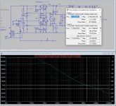
Frequency response, phase response and group delay were taken in the traditional way.
Similarly, the loop gain graph. (CL = 0, 50nF, 100 nF, 500nF and 2 uF)
Is obtained distortion of a signal with a frequency of 10 kHz in the steady state was obtained using a notch filter.
And although the amplifier does not have a servo control system, it works as an integrator and leads to an offset of up to + -2.5 Volts at low frequencies.
I believe that it is the group delay and its behavior both in the audio band and beyond the band at least up to 1 MHz that has the greatest influence on the difference in the sounds provided by the amplifiers.


In the Hafler test, a comparison is made between the output voltage of the model and the normalized input voltage. before applying to the input of the amplifier, all signals are processed by a 100 kHz low-pass filter


One day, a familiar saxophonist musician invited me to his concert in one of the halls of the city. During the concert, the musician went into the hall between rows of chairs. After the concert, the musician asked me a question: “why, while moving away (approaching) from the stage, did the sound timbre constantly change in waves? Some frequencies then weakened, then amplified. I had to go with him to the stage to the acoustic systems and show that the separate enclosures of the acoustic systems (especially the midrange and treble sections) were installed illiterately - the acoustic centers clearly did not match.
Frequency response, phase response and group delay were taken in the traditional way.
Similarly, the loop gain graph. (CL = 0, 50nF, 100 nF, 500nF and 2 uF)
Is obtained distortion of a signal with a frequency of 10 kHz in the steady state was obtained using a notch filter.
And although the amplifier does not have a servo control system, it works as an integrator and leads to an offset of up to + -2.5 Volts at low frequencies.
I believe that it is the group delay and its behavior both in the audio band and beyond the band at least up to 1 MHz that has the greatest influence on the difference in the sounds provided by the amplifiers.
In the Hafler test, a comparison is made between the output voltage of the model and the normalized input voltage. before applying to the input of the amplifier, all signals are processed by a 100 kHz low-pass filter
Last edited:

If you short-circuit the capacitor in the NFB circuit, then the oscillations of the constant component decrease by 2.5 times. This is exactly what the developers of some models of Harman Kardon amplifiers did.

A sinusoidal alternating voltage can be represented using a vector of constant magnitude rotating at a constant angular velocity. The addition of sinusoidal signals of the same frequency shifted in time (as well as subtraction) does not lead to nonlinear distortions in the steady state - only linear distortions occur: the amplitude of the total signal and its phase change. Distortions in the shape of the total signal occur only at the beginning and end of the burst, if the signals are added in the form of bursts.
Distortions in amplifiers associated with the delay occur every time at the moments of change in both the amplitude of the vector and the frequency of its rotation (the angular velocity of rotation of the vector), that is, at the moments of change in dV / dt other than the sinusoidal voltage.
The sound signal is not sinusoidal, the notes of different instruments have the same fundamental tuning frequency, but they have a different set of harmonics up to 18. Of these, the first 7...9 harmonics are the most important for timbre formation. Each harmonic must have its own amplitude and be strictly in its place.
It is known that the magnetic recording of a note of one instrument sounds differently when played in the forward and reverse directions, although it contains the same spectrum.
Even slight changes in the group delay (tPD) lead not only to a delay of the output signal in time (as it seems at first glance), but also to changes in its structure - to subtle changes in both the amplitude of the individual harmonic components of the signal and their phase, to the emergence of new harmonic components. This is especially true of higher harmonics to which hearing is most sensitive.
It is the signal delay that has the greatest impact on the sound quality. This was clearly shown by Bob Carver (https://www.stereophile.com/content/carver-challenge), who, using the David Hafler SWDT test, brought the characteristics of a transistor amplifier closer to those of a tube amplifier and thereby made their sound quality identical. He showed that if the vector errors in the entire audio range do not exceed -60 dB, then it does not matter on which active components the amplifier is made: on lamps or on transistors.
I am convinced that for the designer of audio amplifiers, the normalized input signal should be the main reference. In this case, in the entire audio range, the output signal of the developed amplifier must meet the requirements of the SWDT test. Only in this case will high sound quality be achieved.
I noticed that the "errors" in your 20Hz bursts (~2Hz) are similar to those known as first cycle distortion in that they fall outside the audio spectrum. So, I would say they are not valid audio signals and of no interest to audio system design. Yes, you can connect an audio amplifier to a signal generator that creates these signals, but we spend little or no time listening to signal generators. We listen to music which contains no such frequencies or waveforms.
Hello Bob
As you know I built a complementary mirror loaded LTP following image 9.20 page 215 of your book second edition and tried to maximize shunt resistors R11 R15 to increase LoopGain but experienced high VAS current variations.
With 4k7 ohms it sounds really detailed in the HF but looses a bit of control in the bass compared to my other build that uses a differential VAS (my other build according to fig 9.15 in your book)
Now I simulated another version of the complementary LTP without the vas current setting shunt resistors.
In this case I used a ccs that sets a fixed voltage in the bases of the VAS "helper" transistors.
The resulting simulation gives very good results but I do not know if it will work in reality.
Would you care to comment my new schematic ?
I did not have the time to include the models directly in the asc file so I am posting the models I use as a txt file.
Attachments

If I understand correctly, you do not like the distortion of the first period. In that case, I have 2 questions for you:I noticed that the "errors" in your 20Hz bursts (~2Hz) are similar to those known as first cycle distortion in that they fall outside the audio spectrum. So, I would say they are not valid audio signals and of no interest to audio system design. Yes, you can connect an audio amplifier to a signal generator that creates these signals, but we spend little or no time listening to signal generators. We listen to music which contains no such frequencies or waveforms.
1. From what period do you think the amplifier should accurately amplify the signal?
2. Since what period do you personally listen to music?
How this makes me feel:
YMMV
Jan
'Would you please spend an hour or so of your spare time for this?'Would you care to comment my new schematic ?
I couldn't spare a few minutes to make it easier for you.I did not have the time to include the models directly in the asc file so I am posting the models I use as a txt file.
YMMV
Jan
This is what the simulator shows when measuring non-linear distortion at a frequency of 20 Hz in steady state. In one of the articles, Lynn Olson called such testimony complete nonsense.

we will measure the dependence of the total non-linear distortion (THD) on frequency at an output power of 100 W at a load of 8 ohms on the 2nd and 10th periods


Let's try to figure out how the signal propagation delay time affects other types of distortion other than non-linear ones.
We will test an amplifier that meets the Hafler SWDT requirements to some extent.
From the 10 kHz burst test, it can be seen that the speed distortion does not exceed the 2nd harmonic (below the harmonic distortion in steady state).

 In the test with a triangle signal opposite the positive peak, we also see a higher level of distortion, but this is not so much speed distortion as distortion associated with the 2nd harmonic.
We will test an amplifier that meets the Hafler SWDT requirements to some extent.
From the 10 kHz burst test, it can be seen that the speed distortion does not exceed the 2nd harmonic (below the harmonic distortion in steady state).
Better watch out. He's already typing in PGP schematics in to his simulator.He’s back.
For a music or any other real audio signal, there is no first cycle etc, because real audio is not the product of a linear signal and a rectangular gating pulse. It may be gated once by a mute function and minutes later, it is still on and all out-of-band signals are history, not part of the audio presentation. The recording process removes any out-of-band signal, so that task does not fall to the amplifier.If I understand correctly, you do not like the distortion of the first period. In that case, I have 2 questions for you:
1. From what period do you think the amplifier should accurately amplify the signal?
2. Since what period do you personally listen to music?
- Home
- Amplifiers
- Solid State
- Bob Cordell's Power amplifier book