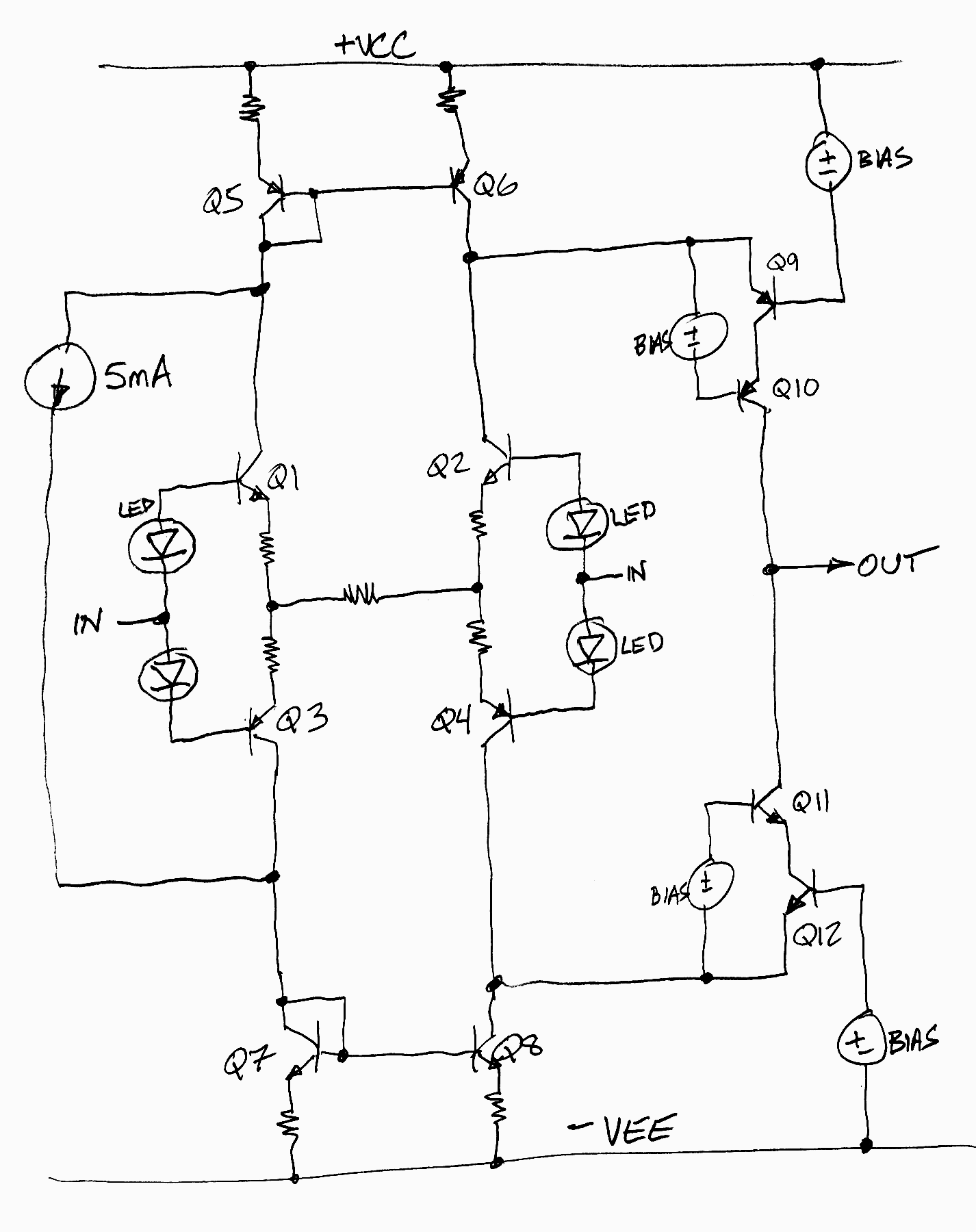
I bought Kolinummi's book from the Linear Audio website and I encourage others to buy it too. On page 200 he saysThe complementary symmetric input stage topology makes it easier to create a symmetric VA-stage. In such a circuit, asymmetric input-stage loading can be accepted without increased distortion, and this topology is also superior in terms of offset voltage, input current, and PSRR.One of his examples of this idea appears on page 194. Not wanting to upload copyrighted material, I have redrawn it by hand, and made some (very!) slight changes; thus it's not a copy. Trust me, the schematic below faithfully represents the essence of his example. Or if you don't trust me, open the book to page 194 and find all of the differences. Maybe you won't agree they are very slight (?)
_
Óñèëèòåëü ñèììåòðè÷íûé ñ êàñêàäàìè óñèëåíèÿ ïî íàïðÿæåíèþ ñ îáùåé áàçîé
Such circuitry has been developed and our fans. I suspect it is a painted one and the same person.
Here is a very small loop gain. It's a dead end.
Attachments
Last edited:
Best Russian amplifier - here: Ñîáèðàåì ñâåðõëèíåéíûé óñèëèòåëü Ñåðãåÿ Àãååâà..
It may seem a bit complicated. 🙂 You can download the files without any problem.
Of the simpler amps have this circuitry:
http://forum.vegalab.ru/attachment.php?attachmentid=234997&d=1429687343
The earlier and more simple version of this amplifier is attached.
Those, who doubt the accuracy of the calculations of the simulator, can draw these two schematic and make the test: the first version has 0.005% distortion, and the last 0.001%. My test showed a perfect match with the parameters, that showed the author.
Attachments
I assume you are referring to cascodes where the cascode bases are fed with the common-mode signal presented to the differential pair, such as using a buffered version of the tail voltage or a replica of the feedback signal?
I have used the replica feedback approach to drive the cascodes, and it works great. It is especially helpful when high-capacitance JFETs are used in the IPS, like the LSK389.
Can you direct us to the place where that quote came from?
Cheers,
Bob
See page 200-201. Summary.
Audio Power Amplifiers. Towards Inherently Linear Amplifiers.
by Dr. Arto Kolinummi. Publ by Linear Audio.
THx-RNMarsh
the Yahoo LTspice group is the best online support, however you do need to join
and Yahoo Group navigation was broken by the "infinite scroll" UI, apparently no consideration for archival or reference related use cases, blew away previous funtionality
and Yahoo Group navigation was broken by the "infinite scroll" UI, apparently no consideration for archival or reference related use cases, blew away previous funtionality
Scott, run an LTSPICE ".op" analysis. Then ignore the stupid terminology and click View ---> Spice Error Log. Mentally substitute "error log" equals "output listing".
OK Thanks. I see other thing appear there too.


Hi Pete,
Yes, I have studied it, and even have plans to touch on it in my second edition. It is indeed an interesting design. As you correctly point out, it is essentially a CFP output stage with what I call an emitter follower "helper"; as the CFP input transistor draws current to turn on the upper PNP CFP output transistor, the emitter current of the CFP input transistor is used to drive the output emitter follower. Ideally, the two output transistors make equal contributions to the output current. One good feature claimed is that the driver transistor does double duty - the same current flowing through it serves the base drive needs of 2 output transistors.
Of course, the Bryston stage can also be viewed as a 2EF output stage with a PNP "helper" transistor that contributes output current when the driver conducts current by tapping into the driver collector and using it to turn on the PNP "helper".
For proper operation, the PNP output tranwsistors and the NPN output transistors generally have to be matched in current gain.
As shown in the schematics you provided, the output stage is a bit more complex than I have described here, it having current gain on the order of a Triple and it also having voltage gain. The voltage gain is also a claimed advantage, since the VAS need not swing as much and has more headroom as a result. Of course, there have been several CFP output stage designs in the past that configured the CFP to provide some gain for the same reason. Alas, VAS distortion is usually much less of a problem than output stage crossover distortion.
Cheers,
Bob
Hi Bob,
I forgot to ask you if you noticed my finding of very high reverse Vbe (>10V) on the driver transistors especially in clipping. I believe that this is one failure mode of the Tiger amps at least, but it is also seen in the Bryston amps:
http://www.diyaudio.com/forums/solid-state/301321-bryston-3biii-spice-simulation.html#post4930009
http://www.diyaudio.com/forums/soli...-tiger-improved-simulation-2.html#post2585028
Hi Pete,
I believe this can happen in any CFP output stage with gain, IIRC, unless steps are taken to avoid it. I think I may have touched on a similar design issue that can occur in class G output stages unless they are properly designed.
In a CFP with gain, each side has essentially an attenuator to ground from the output of the CFP to the emitter of the driver; this is what gives it gain. When one side is off, especially in clipping, the VAS will try to drive the base of the off-side driver to the negative rail, but the attenuation back to its emitter only takes its emitter half way to the negative rail, if for example, the gain of the output stage were set to 2. In this simplified example, the reverse Vbe on the driver might be on the order of half the rail voltage.
Output stages with gain were once a neat idea because they eased the amount of swing required of the VAS and gave it more headroom, but nowadays VAS distortion is not usually the biggest contributor to the kinds of distortion that are hard to get rid of, and the extra bit of headroom in clipping that might result is probably not worth it for a couple more watts at clipping.
If you are going to do a CFP output stage anyway (definitely not my personal preference), one could consider configuring it with gain slightly greater than unity, perhaps 1.1 or 1.2, to give the VAS a bit more headroom and perhaps not have the excessive reverse-Vbe problem.
There may be some of these kinds of issues in other types of output stages under short-circuit conditions or in stacked stages with only unity gain.
Cheers,
Bob
Bob, have a look at the Kolinummi power amp book {sold on the Linear Audio website} pp. 232-233 and especially Fig 7.36
The simplified schematic used by Canadian manufacturer Bryston is presented in Figure 7.35. This circuit has some gain which is set with resistors R1 and R2. The transistors in the circuit remain forward biased at all times and the circuit can be thought of as non-switching even if transistor currents may go close to zero. Linearity also remains good at high frequencies and the mentioned problems of the conventional CFP are avoided.
The simulated power device currents of the three output stages discussed [CFP, EF, Bryston] are plotted in Figure 7.36. [CFP is poopy, EF is slightly less poopy] and the Bryston topology has a very wide and smooth transition.
The simulated power device currents of the three output stages discussed [CFP, EF, Bryston] are plotted in Figure 7.36. [CFP is poopy, EF is slightly less poopy] and the Bryston topology has a very wide and smooth transition.
Bob, have a look at the Kolinummi power amp book {sold on the Linear Audio website} pp. 232-233 and especially Fig 7.36
The simplified schematic used by Canadian manufacturer Bryston is presented in Figure 7.35. This circuit has some gain which is set with resistors R1 and R2. The transistors in the circuit remain forward biased at all times and the circuit can be thought of as non-switching even if transistor currents may go close to zero. Linearity also remains good at high frequencies and the mentioned problems of the conventional CFP are avoided.
The simulated power device currents of the three output stages discussed [CFP, EF, Bryston] are plotted in Figure 7.36. [CFP is poopy, EF is slightly less poopy] and the Bryston topology has a very wide and smooth transition.
Thanks, Mark!
Cheers,
Bob
Hi Pete,
I believe this can happen in any CFP output stage with gain, IIRC, unless steps are taken to avoid it. I think I may have touched on a similar design issue that can occur in class G output stages unless they are properly designed.
In a CFP with gain, each side has essentially an attenuator to ground from the output of the CFP to the emitter of the driver; this is what gives it gain. When one side is off, especially in clipping, the VAS will try to drive the base of the off-side driver to the negative rail, but the attenuation back to its emitter only takes its emitter half way to the negative rail, if for example, the gain of the output stage were set to 2. In this simplified example, the reverse Vbe on the driver might be on the order of half the rail voltage.
Output stages with gain were once a neat idea because they eased the amount of swing required of the VAS and gave it more headroom, but nowadays VAS distortion is not usually the biggest contributor to the kinds of distortion that are hard to get rid of, and the extra bit of headroom in clipping that might result is probably not worth it for a couple more watts at clipping.
If you are going to do a CFP output stage anyway (definitely not my personal preference), one could consider configuring it with gain slightly greater than unity, perhaps 1.1 or 1.2, to give the VAS a bit more headroom and perhaps not have the excessive reverse-Vbe problem.
There may be some of these kinds of issues in other types of output stages under short-circuit conditions or in stacked stages with only unity gain.
Cheers,
Bob
Right, I knew that all CFPs with gain would have the issue, I wasn't sure if Bryston had
anything added to protect the transistors until I entered the schematic into the simulator
and had a close look at it. A few members here at DIYaudio suggested and simulated
some fixes back in the Tiger thread but I've not looked at them in years. I also considered
much lower gain and it might be a good compromise.
I'm sure that most here know that SPICE does not simulate the reverse Vbe breakdown so
we see no reverse current and the full voltage that would be applied if the transistors did
not breakdown.
Last edited:
Bob, have a look at the Kolinummi power amp book {sold on the Linear Audio website} pp. 232-233 and especially Fig 7.36
The simplified schematic used by Canadian manufacturer Bryston is presented in Figure 7.35. This circuit has some gain which is set with resistors R1 and R2. The transistors in the circuit remain forward biased at all times and the circuit can be thought of as non-switching even if transistor currents may go close to zero. Linearity also remains good at high frequencies and the mentioned problems of the conventional CFP are avoided.
The simulated power device currents of the three output stages discussed [CFP, EF, Bryston] are plotted in Figure 7.36. [CFP is poopy, EF is slightly less poopy] and the Bryston topology has a very wide and smooth transition.
Mark, I don't have that book, was the "smooth transition" a result of the configuration
with gain or the helper power transistor where there are both NPN and PNP on both
sides of the output stage?
Do you have any thoughts on the reverse Vbe issue?
Edit: If the drivers have reverse Vbe then they have to be turned off for part of the cycle,
so I'm not sure if that author is correct. I'll have to buy the book and take a closer look
at his analysis.
Last edited:
Dan (djoffe) and David (davada) on this forum came up with some interesting potential
solutions to the problem. Diode clamps from the amp output to the VAS base seem to
help a lot in the old Universal Tiger but not a 100% fix. I think that also lowering the gain
to 1.5 might just do it:
http://www.diyaudio.com/forums/soli...-tiger-improved-simulation-7.html#post2587760
This amp has the input and output sections on the same rails required for the diode
clamp to work.
PB2, I hope you decide to buy the book (from the Linear Audio website), it contains lots of food for thought and, in my opinion, is a good value.
I'm going to buy it but I want to see if there are any other back issues that are worth buying at the same time.
No opinion on the reverse Vbe issue?
The Universal Tiger used 100 ohm resistors in the feedback network whereas the Bryston
with the triple use 2.2K so the reverse Vbe current is much lower. Any idea how much
current is required to destroy or damage a med power device?
No opinion on the reverse Vbe issue?
The Universal Tiger used 100 ohm resistors in the feedback network whereas the Bryston
with the triple use 2.2K so the reverse Vbe current is much lower. Any idea how much
current is required to destroy or damage a med power device?
PB2, I hope you decide to buy the book (from the Linear Audio website), it contains lots of food for thought and, in my opinion, is a good value.
I have this book. It is as you say good value and contains loads of tips for optimisation that I had never considered. A good add on for Bob's book. Recommend it as well.
Paul
I have this book. It is as you say good value and contains loads of tips for optimisation that I had never considered. A good add on for Bob's book. Recommend it as well.
Paul
I'll definitely buy it and cite it in my second edition where appropriate.
Cheers,
Bob
- Home
- Amplifiers
- Solid State
- Bob Cordell's Power amplifier book