Hi David,
SOA protection. You set those using an oscilloscope with the amp running into a load. PITA to set and seldom out of adjustment unless "Terry twiddle" has been in there.
-Chris
SOA protection. You set those using an oscilloscope with the amp running into a load. PITA to set and seldom out of adjustment unless "Terry twiddle" has been in there.
-Chris
I think it was "Harmonic" something or other. My memory will likely remember the rest while I'm sleeping tonight.
Getting old sucks ...
mlloyd1
Getting old sucks ...
mlloyd1
Hi Pete,
... I forget what HTA stood for now.
-Chris
Harmonic Time Alignment.
Nakamichi HTA and MOSFETS amps | Audiokarma Home Audio Stereo Discussion Forums
Nakamichi HTA and MOSFETS amps | Audiokarma Home Audio Stereo Discussion Forums
Hi David,
SOA protection. You set those using an oscilloscope with the amp running into a load. PITA to set and seldom out of adjustment unless "Terry twiddle" has been in there.
-Chris
Ah yes Terry Twiddle.
I know him.
Ah yes Terry Twiddle.
I know him.
Take a look at the two transistors used for current limiting, there's HF compensation in a
number of places, looks like stability issues even around that loop!
The transistors near the pots see a very large Vce, I wouldn't doubt that they are close
to their own SOA limits when they hard limit. They could have sensed right at the emitter
degeneration resistors and made it much simpler.
I just found that there were 5 service bulletins that included upgrading the driver and
output transistors, and lowering the bias current by 1/2 for the 250 version.
Actually the output stage just has current limiting, set at 9 Amps peak in the 250 which
doesn't save it from an output short where they see high voltage and current. Even if
MJ21193/4 were used they can do 8A total at 50V if they are cold, less hot with derating
so obviously 9A is enough to fry them, which it is known for with a shorted output.
Last edited:
Take a look at the two transistors used for current limiting, there's HF compensation in a
number of places, looks like stability issues even around that loop!
The transistors near the pots see a very large Vce, I wouldn't doubt that they are close
to their own SOA limits when they hard limit. They could have sensed right at the emitter
degeneration resistors and made it much simpler.
I just found that there were 5 service bulletins that included upgrading the driver and
output transistors, and lowering the bias current by 1/2 for the 250 version.
Actually the output stage just has current limiting, set at 9 Amps peak in the 250 which
doesn't save it from an output short where they see high voltage and current. Even if
MJ21193/4 were used they can do 8A total at 50V if they are cold, less with derating so
obviously 9A is enough to fry them, which it is known for with a shorted output.
Q505, Q506 Page 10.
Yes there is a lot of compensation. There are two gain stages.
Last edited:
Bob,
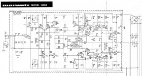
Have you seen the Marantz 250 or 1200 power amp topology? CFP output with a VAS in the output stage and sort of an AC virtual ground input to the output stage allowing the front end to run on a lower supply. Here's the 1200 service manual that has nearly the same schematic as the 250 but easier to read, in .pdf if you are interested:
http://www.vintageshifi.com/repertoire-pdf/pdf/telecharge.php?pdf=Marantz-1200-Service-Manual-1.pdf
I'm not saying that it is good, just different and interesting.
Output stage might be interesting with an OP amp front end.
Hi Pete,
Thanks for putting this up. I had not seen it before. I just took a brief look at it and see some stuff I don't yet understand. Maybe I am missing something in my quick look. It appears that there is the conventional Thompson topology up front with a single-ended VAS (Q503, 504), but with no bias spreader. It then looks like it feeds a push-pull VAS (Q507, 508) with an approximate 2Vbe bias spreader, then feeding the CFP output stage (just a double, not a Triple). Haven't yet figured out the relationship and interconnection between the two VASs I see. Maybe I need to look more closely at the power supply voltages. Not sure about the establishment of desired operating bias of the second (push-pull) VAS.
I also notice that the input differential pair is not degenerated, making me wonder about slew rate and SID.
Cheers,
Bob
Hi Pete,
Yes, you're right on this one. Straight current limiting. On other models it is SOA protection. I was running off memory as soon as I saw that it was the two pots that was being referred to.
Normally a direct short is an uncommon event. Where the main problems seem to come from wiring installed into walls or ceilings. We didn't get very many of these in with blown output stages otherwise.
Pete, can you either post links or the modification sheets here? I haven't got those anymore. I did have them on paper, but they went with the shop when I sold it.
-Chris
Another interesting aspect is the feedback appears to be nested in two loops. Global and to the second VAS. I find the Marantz stuff to be a bit of a brain twister.
H David,
I'll have to look at this one again. I only looked at what I needed to answer the question.
Most Marantz circuits are very straight forward, but then I was trained in that environment. If there are in fact two loops, the inner loop would be to compensate the output stage. I'll have a peek at it.
-Chris
Edit:
I'm trying to find the nested loop. Can you give me a couple component location codes to hunt by?
Chris, the manuals and additional info are here at AK, pages 6 and 9, too bad they are
not in folders there:
AK Database PDF Gallery - Marantz
Let me know if you have any trouble accessing.
I have a 250M that worked for many years, owner had a shorted output, blew, paid for
a repair, blew again. I don't trust the two gain stages, sprinkled in compensation and
the fact that it won't handle a short. Others here have repaired them and told similar
stories of them failing again within a year.
One channel still works in this one, so I could take some measurements but I'll have to
get very curious about it to do so.
H David,
I'll have to look at this one again. I only looked at what I needed to answer the question.
Most Marantz circuits are very straight forward, but then I was trained in that environment. If there are in fact two loops, the inner loop would be to compensate the output stage. I'll have a peek at it.
-Chris
Edit:
I'm trying to find the nested loop. Can you give me a couple component location codes to hunt by?
Hi Chris,
If you look at page 7 of the manual it shows the feedback path. There is FB to the input dif stage and also to the input of the second VAS.
It has similarities to a composite amplifier arrangement and probably has similar compensation.
Last edited:
Marantz 1200B
Looks like the 2nd VAS is inverting the audio signal, so any signal fed back through the local feedback R520(100k)/C509(36pF) and with the given component values it appears to attenuate the local HF gain around 2nd VAS and OPS.
Looks like the 2nd VAS is inverting the audio signal, so any signal fed back through the local feedback R520(100k)/C509(36pF) and with the given component values it appears to attenuate the local HF gain around 2nd VAS and OPS.
Attachments
Hi Pete,
Thanks much! No trouble at all. I used to have all of these manuals.
If you repaired one and it blew again a year later, I have to know. Did you substitute any transistors at all? I only ask because I've repaired many and not had a problem with them coming back. I can think of one excellent reason why you might lose these on a yearly basis. New Years eve party. Don't laugh, it happens. This is often the one time a stereo is ever really cranked up by some folks.
If you look at it logically, what kind of fault would take an entire year (even approximately) to cause a failure of an output stage? The guys who set warranties really want to know. If it was oscillation, you would catch it before the amp left. I had one customer that would add another pair of 4 ohm speakers to his system once a year. Just once (New Years Eve again). He thought his receiver could handle two sets of 4 R speakers because it had "A" and "B" outputs. He thought his receiver had 4 amplifiers in it.
-Chris
Hi Dave,
Does that diagram give you a headache? It looks like a confused football play to me. I never look at that diagram, ever.
I see what you are talking about. There is really only one Vas. The second Vas is really a buffer with gain. You need to think of it that way or become hopelessly confused. The diagram on page 18 should shed some light on this. If you look at the capacitor (C509- 36pF), it's only there for HF stability. So the cap doesn't bypass R520 (100K) for signal. The summing junction has the feedback signal through a 100K resistor (R520) and the forward gain path uses 300R (R521). The feedback signal doesn't have that much to say over what goes on there. You're right in that the buffer unloads the real Vas that has a limited voltage swing. The buffer that follows allows a full voltage swing, but it is a buffer with gain, not a voltage amplification stage in the classic sense.
I have to say that all those arrows really get to you. Don't look at page 7. It's bad for you. It doesn't help that they showed C509 as an electrolytic capacitor. I think it is a mica capacitor if memory serves.
-Chris
Hi Pete,
Thanks much! No trouble at all. I used to have all of these manuals.
If you repaired one and it blew again a year later, I have to know. Did you substitute any transistors at all? I only ask because I've repaired many and not had a problem with them coming back. I can think of one excellent reason why you might lose these on a yearly basis. New Years eve party. Don't laugh, it happens. This is often the one time a stereo is ever really cranked up by some folks.
If you look at it logically, what kind of fault would take an entire year (even approximately) to cause a failure of an output stage? The guys who set warranties really want to know. If it was oscillation, you would catch it before the amp left. I had one customer that would add another pair of 4 ohm speakers to his system once a year. Just once (New Years Eve again). He thought his receiver could handle two sets of 4 R speakers because it had "A" and "B" outputs. He thought his receiver had 4 amplifiers in it.
-Chris
No, I didn't repair it that's just the story I was told about the history.
The thing is that an amp with protection should take shorts, or 2 ohm loads, doesn't
have to sound good but it should survive.
Hi Pete,
Most amplifiers will not take a short. The action of the current limiter is almost always delayed so that music signals with some speaker loads can reproduce the odd high current spike without limiting. If a direct short is applied across the output, the resulting current spike is only limited by the entire circuit impedance. This will normally result in one or more shorted outputs long before protection will act. The high current is allowed to flow out the output and / or driver base circuits which blows the heck out of the protection transistors. Snap ..crack! The blown protection transistors is proof that they did come on at some point in time.
Even if there is no output, a little noise will create a high current pulse by virtue of the fact that the amp is operating in open loop (A short on the output removes the feedback signal), which very quickly becomes a mass extinction event for the output stage.
All owners manuals warn against handling the output wires to the speakers unless the amplifier is turned off. Turned down doesn't always cut it. You can not make a consumer amplifier (for mass distribution) at reasonable prices that will withstand a short on the output every single time.
-Chris
I believe that SOA protection with large caps for delay is to take advantage of the higher pulsed SOA
rating which should be safe for shorts if done right. I also recall Phase Linear, if you can believe it,
having a test where you run the amp at full power and short the output, Crown also had such a test
and perhaps a few others.
I only once shorted my Adcom 555, turned up the volume and just blew fuses - impressive!
Was using them into 2 ohm loads and had increased the fuses to 7 or 8 amps on the rails. Not sure if
the short happened with the 5 or 7 amp fuses.
It would probably be wise to add a speaker or rail fuses to the Marantz 250.
This amp is rated to drive 4 ohm loads and IMO the protection should not trip under those conditions.
It should be able to make use of all the dynamic headroom provided by the large power supply caps,
and never trip under music conditions.
Therefore, assuming a bit of cap droop, and Vbe sat then 50V/4R = 12.5A and I prefer some margin
so it should be set around 15A perhaps even 20A when the Vce is less than about 10V.
Really, it should not trip even for 3 ohm loads since a 4 ohm speaker might dip that low, so I'd
set it to trip with 2 ohm loads, 20 to 25 amps seems about right.
This in combination with rail fuses would probably work into a short. Size the rail fuses for music
conditions, they only see half a cycle so 4 A fast blow would probably work and save it under a short.
Both heat sinks should have thermal cutouts and I'd probably go with 65 deg C.
Last edited:
- Home
- Amplifiers
- Solid State
- Bob Cordell's Power amplifier book