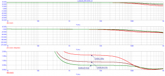
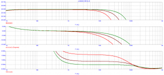
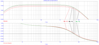
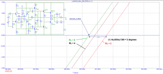
Phase deviation occurs to a greater extent in amplifiers with Miller correction.
When the load changes, the VAS gain changes, along with it, the Miller's dynamic capacitance changes, which causes the phase deviation.
This can be seen on the example of the LANZAR amplifier.
When the load changes, the VAS gain changes, along with it, the Miller's dynamic capacitance changes, which causes the phase deviation.
This can be seen on the example of the LANZAR amplifier.
Attachments
Hi All,
Just wondering what your guys thoughts are on the MJL4281A / MJL4302A VS the MJL3281A / MJL1302A that Bob uses in his BC-1 design. The MJL4281A / MJL4302A seam to have a higher beta and FT.
Just wondering what your guys thoughts are on the MJL4281A / MJL4302A VS the MJL3281A / MJL1302A that Bob uses in his BC-1 design. The MJL4281A / MJL4302A seam to have a higher beta and FT.
I've wondered the same thing. Other than cost, is there any reason not to go with 4281/4302 over 3281/1302
The 3281/1302 have 10% gain matching.
https://www.onsemi.com/pub/Collateral/MJL3281A-D.PDF
https://www.onsemi.com/pub/Collateral/MJL4281A-D.PDF
https://www.onsemi.com/pub/Collateral/MJL3281A-D.PDF
https://www.onsemi.com/pub/Collateral/MJL4281A-D.PDF
I see that in the datasheets - thanks for the info.
So the assumption is that since the 4281/4302 datasheets don't call that out, then we can't assume this. I believe this would only matter if you are running two or more pairs. If you have a single set, then the 4281/4302 devices would be preferred (other than cost). Does that sound right?
So the assumption is that since the 4281/4302 datasheets don't call that out, then we can't assume this. I believe this would only matter if you are running two or more pairs. If you have a single set, then the 4281/4302 devices would be preferred (other than cost). Does that sound right?
I am lead to believe the MJL4281A / MJL4302A are dual die devices to allow for the higher ratings and slightly better specs. Do not know what die they use. There is the additional cost issue as already said. Probably more available because everyone is using the cheaper ones. I see one has a long leadtime on them.
I would think the higher beta, Ft, SOA can only help and not hinder.
We have another BC-1 design done, ready for testing, so we should just try them ourselves and find out for sure.
We implemented the double-cross, so using the MJL4281A / MJL4302A might be to an advantage.
I would think the higher beta, Ft, SOA can only help and not hinder.
We have another BC-1 design done, ready for testing, so we should just try them ourselves and find out for sure.
We implemented the double-cross, so using the MJL4281A / MJL4302A might be to an advantage.
Last edited:
I'd be happy to test a prototype. I have a QuantAsylum QA401 so I could provide some distortion testing
Hi All,
Just wondering what your guys thoughts are on the MJL4281A / MJL4302A VS the MJL3281A / MJL1302A that Bob uses in his BC-1 design. The MJL4281A / MJL4302A seam to have a higher beta and FT.
The most obvious difference is that the voltage rating 4 series is 350V while that of the 3 series is 260V. Power dissipation for the 4 series is a bit higher at 230W as compared with the 3 series of 200 W.
10 mS, 100-V safe area is about the same at about 4 A.
I did not look thoroughly, but I don't see a really big advantage for the 4 series in most amplifiers.
Cheers,
Bob
ThanksI'd be happy to test a prototype. I have a QuantAsylum QA401 so I could provide some distortion testing
Bob has a QA401 too 🙂, I am the one with the old gear
Do we need a beta tester? I think it is too early, they need to be powered up and tested first, I do not want to ship something that might be flawed.
There is the mechanical bits to be figured out, for the 3U dissipante chassis, form, fit, function, hang in there while we work it out.
Hfe mismatch of the outputs can be a significant source of distortion depending on the circuit. If the mismatch is 5%, then you get a 5% 2nd harmonic in the combined base drive current. If your mismatch is 50% you get a 50% 2nd harmonic. I guess the question is whether you want to start with a linear circuit to begin with or do you want to rely on feedback to correct any surprises in exchange for somewhat more durable output transistors.
The drivers will mostly absorb a 5% mismatch in output transistor base current. The 5% change in driver current will result in a much lower percentage change in Vbe of the output transistors and drivers, which is the actual transfer function. A factor of 10 change in base current will only result in about a 10% change in Vbe. That's a reduction by 2 orders of magnitude. (10x change in Ic -> 60 mV change in Vbe)
I would contend that exact beta matching between NPN and PNP is nice to have, but not really that important. As long as output transistor betas all remain above 100, distortion should stay low. That's why I like the modern extended beta devices.
Only when you get back to the VAS stage does mismatch in signal dependent current make much difference. At the output of the VAS, AC current mismatch will translate directly to even harmonic distortion. That's why output triples are better than doubles. You get one more chance to make the loading of the output stage constant versus signal swing.
Having said that, I think the 3281/1302 output transistors are pretty hard to beat, and I am reluctant to use anything else.
Last edited:
You're right for most amps here. The mismatch distortion is still there, just buried (not exactly absorbed). Once you eliminate distortion from the other stages, it becomes significant again. So some amps can still benefit from matched outputs, especially low-feedback types which are less sensitive to the "actual transfer function".
The "actual transfer function" is not singularly important as the phrase suggests. What is important is how distortions, originating in current or voltage, enter the drive current required from the input stage to make the amp work. In one topology the voltage transfer function is important. In another, the current gain function is important. It is up to each of us to determine the truth for the amplifier that is on our bench, not for some other amplifier or generalization of amplifiers.
Ah, I can see my own special form of pedantry is beginning to emerge... Maybe I should just stick to answering questions.
Any thoughts on the emitter degeneration tolerance to distortion other than absolute value? Typically they are specified at 5% tolerance.
For a BJT with Hfe=100, a 10 ohm base resistor is like a 0.1ohm emitter resistor. That's more than 5% of your degeneration voltage if your emitter resistor is 0.22ohm. So I think a 5% mismatch in emitter resistors might actually be minor compared to what the base resistors do.
In any case the final effective emitter resistances play a role in the 2nd harmonic of the voltage transfer curve, but you don't necessarily know whether that 5% mismatch is hurting or actually helping due to mismatches elsewhere.
And all this is dependent on parameters that vary from batch to batch anyway, so some would say just don't bother to quantify it beyond the worst-case values. In the MJL3281/1302 the worst case is not as severe as for the MJL4281/4302.
Last edited:
Base resistors multiply the effect of beta mismatch, whereas emitter resistors reduce it (a little).
Hfe mismatch of the outputs can be a significant source of distortion depending on the circuit. If the mismatch is 5%, then you get a 5% 2nd harmonic in the combined base drive current. If your mismatch is 50% you get a 50% 2nd harmonic. I guess the question is whether you want to start with a linear circuit to begin with or do you want to rely on feedback to correct any surprises in exchange for somewhat more durable output transistors.
The effect of Hfe mismatch in the output stage depends largely on the source impedance to the output transistors. The base current will create a distorted voltage "across" that impedance. However, the details of the effect depend heavily on the circuit configuration, as you suggest. When a 2EF output stage is being used, the amount of total current gain provided is not that great, and will get lower if there is beta degradation at high current. The output impedance of the Miller-compensated VAS will typically come into play as well, and this factor is frequency-dependent due to the shunt feedback of the Miller compensation capacitor.
This is why I always recommend using an output Triple. It changes tremendously the matter of impedance seen looking back from the output transistor bases.
In matters like this, where we speculate about open-loop distortion of an output stage, simulation is our friend. It is the best way to get a clear picture of what is happening. There are many different ways to do this. One example is to drive the drivers and output stage and bias spreader from an impedance the approximates that of the output of the VAS.
Of course, simulating the whole amplifier closed loop and then looking at the distortion at different power levels with different degrees of output stage beta mismatch is also a sound approach.
Cheers,
Bob
For a BJT with Hfe=100, a 10 ohm base resistor is like a 0.1ohm emitter resistor. That's more than 5% of your degeneration voltage if your emitter resistor is 0.22ohm. So I think a 5% mismatch in emitter resistors might actually be minor compared to what the base resistors do.
In any case the final effective emitter resistances play a role in the 2nd harmonic of the voltage transfer curve, but you don't necessarily know whether that 5% mismatch is hurting or actually helping due to mismatches elsewhere.
And all this is dependent on parameters that vary from batch to batch anyway, so some would say just don't bother to quantify it beyond the worst-case values. In the MJL3281/1302 the worst case is not as severe as for the MJL4281/4302.
Yes, base stopper resistors definitely act as if part of the emitter resistor in an output stage. Their presence, if large (10 ohms is large) also degrades thermal stability in regard to current hogging with paralleled output transistors. I use either 4.7 ohms or 2.2 ohms, more often 2.2 ohms when the layout is reasonably tight and bypassing is good. BTW, since the base resistance divided by beta is effectively part of the emitter resistor, biasing to meet the Oliver criteria will be affected somewhat. I almost always use 0.22-ohm emitter resistors, so a base stopper resistor will have some effect on required bias for minimum crossover distortion.
Cheers,
Bob
BTW, since the base resistance divided by beta is effectively part of the emitter resistor, biasing to meet the Oliver criteria will be affected somewhat. I almost always use 0.22-ohm emitter resistors, so a base stopper resistor will have some effect on required bias for minimum crossover distortion.
Thank for that Bob, I certainly didn't know that, and didn't know how the two relate.
- Home
- Amplifiers
- Solid State
- Bob Cordell's Power amplifier book