Excerpt from Douglas Self's book
"Audio Power Amplifier Design" sixth edition,
Common Misconceptions about Negative Feedback
page #57
Limited open-loop bandwidth prevents the feedback signal from immediately following the system input, so the utility of this delayed feedback is limited.
No linear circuit can introduce a pure time-delay, the output must begin to respond at once, even if it takes a long time to complete its response. In the typical amplifier the dominant-pole capacitor introduces a 90° phase-shift between input-pair and output at all but the lowest audio frequencies, but this is not a true time delay. The phrase delayed feedback is often used to describethis situation, and it is a wretchedly inaccurate term.
Only time variant systems can introduce delays, and that’s largely by definition. Audio amplifiers are time invariant systems, meaning that the transfer function is constant in time.
I agree , we can hear records with years of delay .
But what if this delay is not constant?
How big does it have to be for us to perceive it? We are talking about the biggest problems of audio amplification,
the first thing happens , the second thing is that it is very small.
I believe this is called phase intermodulation (PIM).
Bob Cordell wrote a lot about that, worth a read.
Jan
I[/QUOTE]
only in steady state after the end of transientsA delay is not a distortion because no information/harmonic frequencies are added to the signal.
how can you confuse degrees with time?Seems phase shift and propagation delay are sometimes confused.
forr, you can see Douglas Self's favorite correction Cdom work hereExcerpt from Douglas Self's book
Attachments
[/QUOTE]I believe this is called phase intermodulation (PIM).
Bob Cordell wrote a lot about that, worth a read.
Jan
I
this is due to the peculiarities of the loop amplification and, first of all, to the frequency of the first pole
Attachments
Bruno Putzeys
Hypex Electronics, Grimm Audio, The Netherlands
On the occasion of the 123-rd AES Convention, October 6, 2007
Not scientifically established but useful nonetheless:
1. When you’re strapped for loop gain at 20 kHz, limit low-frequency loop gain to the same value.
2. THD becomes higher but constant throughout the audio band.
3. Colouration becomes less obvious and less annoying.
1. So we came to the first pole with a frequency of 20 kHz, and in 97% (if not more) of the released amplifiers it is not higher than 1 kHz.
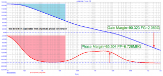
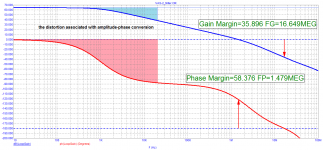
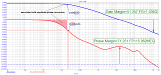
2. Not only is the THD stabilized, but the output impedance becomes constant throughout the audio range. Decreases the phase deviation of the loop amplification in the audio range and, accordingly, the distortion associated with amplitude-phase conversion.
Hypex Electronics, Grimm Audio, The Netherlands
On the occasion of the 123-rd AES Convention, October 6, 2007
Not scientifically established but useful nonetheless:
1. When you’re strapped for loop gain at 20 kHz, limit low-frequency loop gain to the same value.
2. THD becomes higher but constant throughout the audio band.
3. Colouration becomes less obvious and less annoying.
1. So we came to the first pole with a frequency of 20 kHz, and in 97% (if not more) of the released amplifiers it is not higher than 1 kHz.
2. Not only is the THD stabilized, but the output impedance becomes constant throughout the audio range. Decreases the phase deviation of the loop amplification in the audio range and, accordingly, the distortion associated with amplitude-phase conversion.
Attachments
Bob's book teaches how to do this with the addition of a pair of resistors ... so, you could put those resistors on your PCB along with pin header shorting blocks to insert/remove them at will. Then measure and listen (A) with low frequency loop gain >>> 20 kHz loop gain; also (B) with low frequency loop gain == 20 kHz loop gain. Now you're making the decision based on your own experience and your own subjective/objective DATA. Rather than some conference paper's bold assertions made thirteen years ago.
Bruno Putzeys
Hypex Electronics, Grimm Audio, The Netherlands
On the occasion of the 123-rd AES Convention, October 6, 2007
Not scientifically established but useful nonetheless:
1. When you’re strapped for loop gain at 20 kHz, limit low-frequency loop gain to the same value.
2. THD becomes higher but constant throughout the audio band.
3. Colouration becomes less obvious and less annoying.
1. So we came to the first pole with a frequency of 20 kHz, and in 97% (if not more) of the released amplifiers it is not higher than 1 kHz.
2. Not only is the THD stabilized, but the output impedance becomes constant throughout the audio range. Decreases the phase deviation of the loop amplification in the audio range and, accordingly, the distortion associated with amplitude-phase conversion.
Definitely not scientifically proven. This harks back to the de-bunked TIM arguments of the 1970's made by Matti Otala. He made similarly-de-bunked are guments about Phase Intemodulation distortion (PIM).
In particular, the open-loop bandwidth has no effect on modulation of phase. In a feedback amplifier, the closed loop phase is modulated by changes in the closed-loop 3-dB point, not the open-loop corner. This is because ordinary amplitude intermodulation causes across-the-board gain changes in some stages that then cause changes in the closed-loop bandwidth that result in minor phase deviations in the closed loop response. See the paper on PIM on my website. It is important that one recognize that a power amplifier is essentially a minimum phase system.
Cheers,
Bob
Bruno Putzeys
Hypex Electronics, Grimm Audio, The Netherlands.
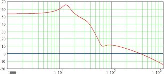
Hypex Ncore loop gain.
Attachments
Bob's book teaches how to do this with the addition of a pair of resistors ... so, you could put those resistors on your PCB along with pin header shorting blocks to insert/remove them at will. Then measure and listen (A) with low frequency loop gain >>> 20 kHz loop gain; also (B) with low frequency loop gain == 20 kHz loop gain. Now you're making the decision based on your own experience and your own subjective/objective DATA. Rather than some conference paper's bold assertions made thirteen years ago.
I did this on my e-Amp. I could go between Miller or TMC and then I could reduce the overall loop gain to flatten it out to about 40 kHz (IIRC). All done with 2 pin jumpers.
I still had my original 280W Miller comp'd amp from 2006 and then the 180 W e-amp (2011/2012) with TMC etc when I was living in Taiwan. A local guy came around to take a listen and preferred the older amp even though it had a lot more distortion (I got it measured on an old AP in the lab while in Japan. It was about 0.05% vs the e-Amp which was a lot lower in sim but never measured).
Who knows what sounds best? I learnt not to get to het up on this subject - high road to nowhere.
🙂
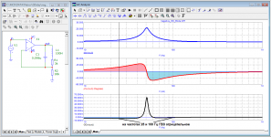
Phase shift and group delay are completely different concepts. The group delay can be negative in a certain frequency range, while the phase shift can be both negative and positive, depending on the frequency: to the left or to the right of the group delay surge (overload).Seems phase shift and propagation delay are sometimes confused.
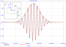
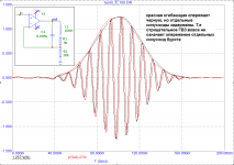
Here is a real example
At 100 Hz, the group delay is negative (the envelope of the output red signal is ahead of the envelope of the input black signal), and the phase of the output signal is lagging.
At 25 Hz, the group delay is also negative (the envelope of the output red signal is ahead of the envelope of the input black signal), but the phase of the output signal is ahead
Attachments
Petr_2009,
I would agree that we may not consider envelope reproduction accuracy as much as we might.
I would agree that we may not consider envelope reproduction accuracy as much as we might.
Phase shift and group delay are completely different concepts. The group delay can be negative in a certain frequency range, while the phase shift can be both negative and positive, depending on the frequency: to the left or to the right of the group delay surge (overload).
Here is a real example
At 100 Hz, the group delay is negative (the envelope of the output red signal is ahead of the envelope of the input black signal), and the phase of the output signal is lagging.
At 25 Hz, the group delay is also negative (the envelope of the output red signal is ahead of the envelope of the input black signal), but the phase of the output signal is ahead
This is all well and good, and we must always be mindful of the difference, but we must also be mindful of the magnitudes of these effects in the audio band. PIM, for example, is real, but it can be remarkably small, and largely has nothing to do with where the open-loop pole is in the NFB open loop.
For some perspective, you should take a look at a second-order or 4th order Linkwitz-Riley speaker crossover.
Cheers,
Bob
Definitely not scientifically proven. This harks back to the de-bunked TIM arguments of the 1970's made by Matti Otala. He made similarly-de-bunked are guments about Phase Intemodulation distortion (PIM).
In particular, the open-loop bandwidth has no effect on modulation of phase. In a feedback amplifier, the closed loop phase is modulated by changes in the closed-loop 3-dB point, not the open-loop corner. This is because ordinary amplitude intermodulation causes across-the-board gain changes in some stages that then cause changes in the closed-loop bandwidth that result in minor phase deviations in the closed loop response. See the paper on PIM on my website. It is important that one recognize that a power amplifier is essentially a minimum phase system.
Cheers,
Bob
Hi Bob,
The context of this was that Bruno is fully on the same page as you are. Then he went on to say that 'if you are strapped for loop gain at 20kHz' you can do some things to ameliorate the negative effects.
This was then taken out of context to support some case, to present it as if Bruno preferred those conditions, which is misleading.
Jan
On this occasion, I will give an example from my practice.For some perspective, you should take a look at a second-order or 4th order Linkwitz-Riley speaker crossover.
Cheers,
Bob
I was invited to investigate the reasons for the bad sound in a university hall that used 3-band amplification. Three amplifiers had crossovers at the inputs with switchable and adjustable section frequencies. One crossover frequency was set in the range of 50 ... 100 Hz, the second - 1 ... 5 kHz. The frequency response for sound pressure was adjusted using a multi-band equalizer and an analyzer. However, no adjustments were made to get good sound quality. What happened: the signal was processed by amplifier crossovers and a multi-band equalizer to equalize the frequency response curves of acoustic systems that do not fit well with each other. As a result, the audio signal underwent a triple transformation by filters.
I started by checking the frequency response of individual loudspeakers and flattening their frequency response in the passband using passive crossovers inside the enclosures and replacing the drivers with more suitable ones. The lowest-frequency acoustic systems forced the sound engineer to modify by installing additional struts and stiffeners inside the cases.
After equalizing the frequency response of individual speaker systems with good overlap of each other's bands, the optimal crossover frequencies were determined, which were then used in the amplifier crossovers.
Only after that, music began to sound in the hall. All EQ controls had to be set to the middle position. As a result, there is no need to use an equalizer. The equalizer has been removed from the path, the signal path has become shorter and the sound quality has become even better.
Not surprisingly, many good sound lovers prefer to use speakers with the simplest first-order filters, or even full-range loudspeakers without any filters.
is there a phase plot for the Hypex? That looks challenging to stabilize.
Hi Demian
It is almost impossible to stabilize it when it's coming out of clipping so one have to "knock out" one active pole.
To have a look at the phase plot(s) you should download the following
Whitepapers from: Hypex application notes and whitepapers
Ncore technology whitepaper
GLOBALLY MODULATED SELF-OSCILLATING AMPLIFIER WITH
IMPROVED LINEARITY
You can also read the Hypex and Purifi audio patents by Bruno.
I can point you to a schematic of a Ncore if you like to see how it's done.
Stein
Hello. Couple of questions.Your attitude to the increase in loop gain. And the use of nested feedbacks .
- Home
- Amplifiers
- Solid State
- Bob Cordell's Power amplifier book