I received my copy a couple of weeks ago. I confess I found a first edition pdf sometime in Spring and browsed through it. It made me decide I would purchase this new edition.
Interesting stuff. The first 4-5 chapters were easy to read and that made me think that would continue to be the case. Not really. I've reached chapter 13 and I understand half of what I read. That's nice. I will go back during the second reading and digest what I need to study.
My only negative comment is: the book is really heavy. Not practical for bed-time reading, which is when I like to do much of mine. But this allows me to joke: There's some heavy stuff in there".
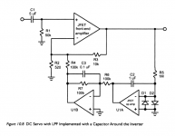
Second Edition: Question / observation about Fig. 10.8 , DC Servos
Hi Bob,
I'm really loving the new edition. Congratulations on a teriffic update to a classic book!
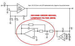
I'd like to offer an observation about the noninverting DC servo shown in Figure 10.8, attached below as Figure 1. My observation is a standard, perhaps hackneyed, religious axiom in DIYaudio: if some is good then more is better! Specifically your opamp U1B implements a first order lowpass filter. But if one is good then two is better (!). Why not use an inverting filter topology like Multiple FeedBack to build a second order lowpass filter? A diagram is shown in the attached Figure 2 below. Expand your browser window to full screen and click the white "X" at lower left to see the images full size.
I wrote the word "Bessel" just to start an argument; I don't think it actually matters whether the filter is Butterworth (zeta=0.5) or Bessel (zeta=0.833) or any other specific "alignment". In my opinion the important details are the cutoff frequency and the order of the filter. Set the cutoff frequency to match the cutoff in Bob Cordell's book, 2nd edition, U1B of Fig 10.8. Set the order of the filter to be two. Done!
What do you think about it?
_
Hi Bob,
I'm really loving the new edition. Congratulations on a teriffic update to a classic book!
I'd like to offer an observation about the noninverting DC servo shown in Figure 10.8, attached below as Figure 1. My observation is a standard, perhaps hackneyed, religious axiom in DIYaudio: if some is good then more is better! Specifically your opamp U1B implements a first order lowpass filter. But if one is good then two is better (!). Why not use an inverting filter topology like Multiple FeedBack to build a second order lowpass filter? A diagram is shown in the attached Figure 2 below. Expand your browser window to full screen and click the white "X" at lower left to see the images full size.
I wrote the word "Bessel" just to start an argument; I don't think it actually matters whether the filter is Butterworth (zeta=0.5) or Bessel (zeta=0.833) or any other specific "alignment". In my opinion the important details are the cutoff frequency and the order of the filter. Set the cutoff frequency to match the cutoff in Bob Cordell's book, 2nd edition, U1B of Fig 10.8. Set the order of the filter to be two. Done!
What do you think about it?
_
Attachments
Last edited:
I'm looking to build and test the amplifier in Bob's book as a learning exercise. I'm putting together a BOM using Mouser.co.uk. I just have a couple of queries.
In Fig 4.1 Q14 is 2SC3503, Q15 is KSC3503. Mouser stocks the KSC but not the 2SC. Are these essentially the same thing though? Similarly Q13 is 2SA1381 whilst Q16 is KSA1381. Again can I just double up on the KSA?
R26 is a variable 1k resistor, but what does the "(240 typ)" mean? Can this be a 1 turn trim pot, or does it need to be something better?
In Fig 4.2 there is a 1.5uH inductor. Mouser has over 50 1.5uH radial lead inductors. Is there anything else I should be narrowing down the search on, such as max DC current? Would this Bourn 652-RLB0913-1R5K be okay for example?
RLB0913-1R5K Bourns | Mouser United Kingdom
Many thanks
2SA/KSA just different manufacturers codes I think.
I think 240 trimmer means 240 degrees rotation?
The inductor needs to be air-cored, otherwise its significantly non-linear and could saturate. You can fabricate this.
I think 240 trimmer means 240 degrees rotation?
The inductor needs to be air-cored, otherwise its significantly non-linear and could saturate. You can fabricate this.
Yes, 2SA/2SC and KSA/KSC are interchangeable. The 2SA/2SC parts are no longer manufactured.
Presumably the "240 typ" means that the trimmer will typically be set to a value of 240 ohms. I prefer to use multi-turn trimmers for precise adjustment but that's probably overkill given the temperature-driven variations of the bias point.
Presumably the "240 typ" means that the trimmer will typically be set to a value of 240 ohms. I prefer to use multi-turn trimmers for precise adjustment but that's probably overkill given the temperature-driven variations of the bias point.
iaaeap, the trimmer R26 is configured as a two terminal variable resistor.
If you were to build 300 copies of this amplifier, for 300 different customers,
In other words, the typical value of R26 in a typical sample of this power amp design, is 240 ohms. It is "240 (typ)"
If you were to build 300 copies of this amplifier, for 300 different customers,
and if you adjusted the trimmer R26 on each amplifier so you get exactly the desired output stage bias current in each of the 300 amplifiers,
and if you now measured the resistance of each of those 300 trimmers after adjustment,
you would find that the most common resistance is 240 ohms.
In other words, the typical value of R26 in a typical sample of this power amp design, is 240 ohms. It is "240 (typ)"
I wish I had the book to refer to the fig 4.1 circuit.
Is it similar to a circuit in the old book that I could refer too?
2SA1381/2SC3503 are the original Sanyo EIAJ part numbers. Fairchild/Onsemi have a dual naming for the second sourced parts, KSA1381/KSC3503 as shown in the data sheets.
240ohm is the nominal set value for an assumed 500 ohm pot. Mark adds that the wiper is shorted to one on the other terminals, cw or ccw to make the variable R.
The 1.5uH inductor is an air core coil, wound using solid enameled magnetic wire. Basically 12 turns, 1" diameter of 18AWG. You do not want a inductor with a ferrite or powered iron core since they saturate and cause distortion.
FYI, I have the amplifier, called "BC-1" in chapter 5 built & operational.
I approached Bob earlier asking if there would be something to build in the new book. The answer was yes and no, there is a complete design but no pcb's available for easy assembly. So, I took it upon myself with Bob's help and encouragement to design a set of pcb's for BC-1. This was done in anticipation that their maybe some interest in book owners wanting to buildup the BC-1 amplifier.
I have sent the pcb's to Bob Cordell for evaluation. Bob graciously offered to review, and now evaluate my design implementation and the build.
Once Bob has given them his approval I will be able to release them for others to use.
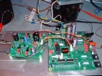
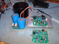
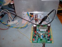
I will attach a pic of the set of pcb's in operation. There is a Mouser BOM in a shopping cart in which you will be able to order the parts against. It will be a complete amp with out the chassis and mechanical bits. A 3 board set, a simple & cost effective, rectifier/filter, BC-1 (AFE), BC-1(OPS).
Since I was on a roll I also did up the DH-200C design as shown in chapters 9 & 14. Bob is also evaluating that one too, like Bob needs more work, especially from me 🙂
Is it similar to a circuit in the old book that I could refer too?
2SA1381/2SC3503 are the original Sanyo EIAJ part numbers. Fairchild/Onsemi have a dual naming for the second sourced parts, KSA1381/KSC3503 as shown in the data sheets.
240ohm is the nominal set value for an assumed 500 ohm pot. Mark adds that the wiper is shorted to one on the other terminals, cw or ccw to make the variable R.
The 1.5uH inductor is an air core coil, wound using solid enameled magnetic wire. Basically 12 turns, 1" diameter of 18AWG. You do not want a inductor with a ferrite or powered iron core since they saturate and cause distortion.
FYI, I have the amplifier, called "BC-1" in chapter 5 built & operational.
I approached Bob earlier asking if there would be something to build in the new book. The answer was yes and no, there is a complete design but no pcb's available for easy assembly. So, I took it upon myself with Bob's help and encouragement to design a set of pcb's for BC-1. This was done in anticipation that their maybe some interest in book owners wanting to buildup the BC-1 amplifier.
I have sent the pcb's to Bob Cordell for evaluation. Bob graciously offered to review, and now evaluate my design implementation and the build.
Once Bob has given them his approval I will be able to release them for others to use.
I will attach a pic of the set of pcb's in operation. There is a Mouser BOM in a shopping cart in which you will be able to order the parts against. It will be a complete amp with out the chassis and mechanical bits. A 3 board set, a simple & cost effective, rectifier/filter, BC-1 (AFE), BC-1(OPS).
Since I was on a roll I also did up the DH-200C design as shown in chapters 9 & 14. Bob is also evaluating that one too, like Bob needs more work, especially from me 🙂
Attachments
Last edited:
Your inductor (12 turns on 1 inch dia) sounds too much for 1.5 uH.
Is this something you have measured?
Is this something you have measured?
Oops it is 1/2" diameter.
I wound mine on a deep socket that is slightly smaller than 1/2" (10-11-12mm?)
Bob wrote to me,
I wound mine on a deep socket that is slightly smaller than 1/2" (10-11-12mm?)
Bob wrote to me,
With respect to the output coil, if convenient, leave a little extra space around it,especially in the length direction, and err on the larger side regarding the spacing of its pads. Right now the coil is 12 turns of 18 AWG, which comes to about 0.5 inch length if tight wound (18 AWG is 0.04" dia), so I'm guessing you are allowing 0.5 or 0.6 in for the pad spacing, the latter being wise. Also, keep in mind that the pads should be at diagonally opposite corners of the footprint rectangle that the coil occupies (coil diameter is 0.5"). That footprint rectangle might therefore want to be something like 0.6 X 0.6. If someone wanted to use 16 AWG, I note that 16 AWG diameter is 0.051 and that 12 turns would come to 0.061, which is about 0.1" longer than an 18 AWG coil.
Last edited:
In Fig 4.2 there is a 1.5uH inductor. Mouser has over 50 1.5uH radial lead inductors. Is there anything else I should be narrowing down the search on, such as max DC current? Would this Bourn 652-RLB0913-1R5K be okay for example?
RLB0913-1R5K Bourns | Mouser United Kingdom
Many thanks
That inductor has a ferrite core, thats not good for audio since it will distort, you should really build your own air core inductor, 1.5uH is not much inductance so a few turns on a air core inductor should suffice.
This web page, created and maintained by an amateur radio hobbyist (of course), includes a "calculator" that tells you a pretty darn good estimate of the inductance of power amplifier output coils you wind yourself. Play around with it!
Inductance Calculation
Inductance Calculation
I'm pleased to say my copy shipped from T&F arrived in Brisbane, Australia last week. Chapter 4 is excellent and I'm discovering other interesting new material while flicking through the pages. Thanks Bob!
A question regarding ANF current sources discussed earlier in this thread. I have put the shunt compensation network proposed by Kiwanuka to good use in my own projects.
I'm interested in understanding how to calculate the optimal values for these components since this is not covered in his paper, which proposes 10R + 3n3 for a control transistor resistor load of approx. 22k. The one in my latest project is an order larger at 220k.
Attachments
Last edited:
@ rsavas - OK that's more like it.
My calculations suggest that would be around 1.4uH. At 1" dia it would be about 3.3uH.
I've used a drill as a spindle to wind such coils on in the past. I don't think it matters too much if it is not exact, but some have reported issues when the inductance is too high when used on capacitive loads (els speakers).
Last edited:
If I use output inductor -ususally not-, I use something like this:
15A 1.8uH Power inductor air core choke-in Transformers from Home Improvement on Aliexpress.com | Alibaba Group
Parallel with 2,2-3,3ohm 5W resistor.
Sajti
15A 1.8uH Power inductor air core choke-in Transformers from Home Improvement on Aliexpress.com | Alibaba Group
Parallel with 2,2-3,3ohm 5W resistor.
Sajti
Vertically mounted air-cores tend to spray their EMI further over the PCB, its better to have
horizontal (or ideally toroidal) arrangement which couple less flux into loops on the PCB.
horizontal (or ideally toroidal) arrangement which couple less flux into loops on the PCB.
Vertically mounted air-cores tend to spray their EMI further over the PCB, its better to have
horizontal (or ideally toroidal) arrangement which couple less flux into loops on the PCB.
Yes. This is why I put it on the protection pcb, close to the output, and far away from the amp pcb.
Sajti
... how to calculate the optimal values for these components since this is not covered in [Kiwanuka's] paper ...
I assume he built the simulation shown in Fig.5 then ran it many times, experimenting with a whole lot of different component values, until he got a result (Fig.8) that he liked.
That Aliexpress source is expensive for the cost of the material. I was using an old common Pioneer double horizontally wound sample as an example for my footprint.
Problem for DIY is getting magnetic wire, at least from the major disti's, to put in a kit. I had some old stuff from my electric motor re-winder apprentice screw up days 🙂, but I see ebay has lots of 1mm(18AWG).
iirc it was something like 45" in length, there is one on line calc that figures this out for you.
Took a file and some 80 grit sand paper to take off the coating to expose the Cu for solder. Better to leave the coil on the socket/drill while taking off the coating.
Happy winding 🙂
This was my first attempts, good enough as you say, I took it a bit further, now with the deep socket trick, they look like machine made, not that it really matters 🙂I've used a drill as a spindle to wind such coils on in the past.
Problem for DIY is getting magnetic wire, at least from the major disti's, to put in a kit. I had some old stuff from my electric motor re-winder apprentice screw up days 🙂, but I see ebay has lots of 1mm(18AWG).
iirc it was something like 45" in length, there is one on line calc that figures this out for you.
Took a file and some 80 grit sand paper to take off the coating to expose the Cu for solder. Better to leave the coil on the socket/drill while taking off the coating.
Happy winding 🙂
Last edited:
- Home
- Amplifiers
- Solid State
- Bob Cordell's Power amplifier book