I think we are in violent agreement other than that fact that this is one of the few threads that gets down and dirty with discussions, so I feel casual consumers need to be dragged along kicking and screaming 🙂
As Bob has mentioned the Whitlock THAT designs are exceedingly good and affordable. I look on them as peace of mind but wont argue with anyone who thinks they are unecessary in domestic settings. Other things are far more important. Gain structure for one (having lived with a matching pre-power combo with way too much gain for a long time), but cakes need icing 🙂.
Secondary benefit is that going to twisted pair signal wiring cuts out 99% of the temptation to use expensive cables as plain old van Damme is as good as anything.
Speaking of THAT ICs, they have dealt with the source end of the balanced issue as well. Referred to by them as "OutSmarts", their IC solution emulates a true floating transformer output, as independent of a ground reference as possible with an active output circuit. If you apply a common mode signal to its output (i.e., common-mode back-drive) very little signal current will flow. This is effectively source common mode rejection. A transformer with a floating output winding has this property.
The great majority of preamplifier balanced outputs are created by taking the internal single-ended output as hot, and running it through an inverter to create cold. This approach obviously has no source common mode rejection.
Cheers,
Bob
Whitlock's 5568561 DIFFERENTIAL LINE RECEIVER WITH COMMON-MODE AC BOOTSTRAPPING
should be public domain by now, > 20 years from issue date - compleltely free to use moraly, legaly - this is the "deal" with patents
another fun option re balanced signal drive is primary R cancellation with mixed feedback to reduce low frequency saturation distortion - shown by Walt in his last opus "Op Amp Applications"
even xfmr balanced lines really want a bleeder gnd connection to prevent insulation breakdown, ESD protection/clamping and overall shield are practical requirements in real world applications
but once inside a PA there really seems to be no reason beond "conceptual art", "eye candy" to continue balanced to the power output
balanced output drive in Class D is a different story
"open at one end" shield termination today is also better done "hybrid" - DC open but RF low L feedtru or C ring to give full 360 RF shield to chassis EMI short - Neutric makes the connectors
Last edited:
But at around $5 for the THAT1646 its not a hardship to buy the silicon. Not sure you could make the circuit for much less for the same performance. But certainly an interesting challenge.
The Neutrik EMC series are interesting, but OTT even for me in the home.
The Neutrik EMC series are interesting, but OTT even for me in the home.
Last edited:
The Neutrik EMC series are interesting, but OTT even for me in the home.
They are good, I use them on mic inputs they make an easily measurable difference in out of band spurs. They were very well thought out, and hard to believe as I heard designed by committee. Never ceases to amaze me they are $8.57 at B&H, Eichmann Bullet snake oil goes for $80 (probably the most tasteless name for a product ever).
Last edited:
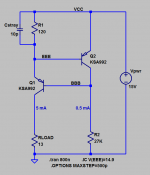
Bob, I took to heart the advice in post #7526 and started simulating the 2T shunt feedback current source in the frequency domain, studying gain and phase. The simulation results seem to be telling me
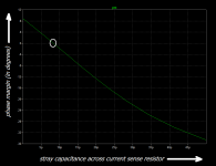
I made a plot of simulated phase margin vs. stray capacitance, image #3 below. As you can see, phase margin crosses zero when Cstray is above 8 picofarads. That's scary!
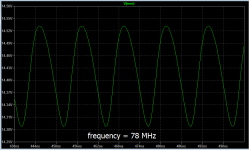
To get the transient simulation results in image #2, I used the LTSPICE directive ".IC" (Initial Conditions) to nudge the simulated circuit away from its metastable state. The LTSPICE deck (.asc file) is attached if anybody wants to horse around with it.
I myself have decided to stop using this particular topology to implement a current source; I've gone to (VREF-VBE)/R circuits, with and without cascode. Mostly, with cascode.
- Self inductance of the transistor pins (up to 15 nH) doesn't make much difference. I didn't study mutual inductance however.
- The impedance of the load driven by the current source is critical. Lower impedance loads (such as the emitters of an LTP) result in MUCH worse phase margin.
- The ratio of currents between the two transistors doesn't make much difference. I froze it at ten to one so you wouldn't gripe.
- Stray capacitance across the current sense resistor ("R1" in the schematic below) can destroy phase margin.
- Different transistor part#s (i.e. different SPICE model parameters) gave different amounts of phase margin. The Fairchild KSA992 (model supplied by Linear Technology) was worst among the PNPs I tried. The BC560C (model supplied by Cordell Audio) was second worst; it needed 30pF of stray cap to begin oscillating.
To get the transient simulation results in image #2, I used the LTSPICE directive ".IC" (Initial Conditions) to nudge the simulated circuit away from its metastable state. The LTSPICE deck (.asc file) is attached if anybody wants to horse around with it.
I myself have decided to stop using this particular topology to implement a current source; I've gone to (VREF-VBE)/R circuits, with and without cascode. Mostly, with cascode.
Attachments
Last edited:
I think "balanced" meaning equal output impedances, these impedances have to be seen from somewhere. When the emitter or the receiver have not a transformer, there is a need of biasing for the active circuits, usually half way of the power supply rails.Just to be clear. A balanced system has no reference to ground at all.
I don't call 'balanced' the input or the output of a single ended transformer. They are "floating" which means without any potential reference.That is part of the fundamental definition of balanced. Even Bruno neglected to mention that. At least in the G word. Best way to understand this is to visualize a transmission path with a single ended transformer at the transmit end and a single ended transformer for the load at the receiving end. There is no reference to ground. If ground is introduced it is no longer balanced. Everything else is differential.
I think "balanced" meaning equal output impedances, these impedances have to be seen from somewhere. When the emitter or the receiver have not a transformer, there is a need of biasing for the active circuits, usually half way of the power supply rails.
I don't call 'balanced' the input or the output of a single ended transformer. They are "floating" which means without any potential reference.
That is the definition of balanced. Floating with out any reference to ground.
Naturally the impedance is balanced. Anything else is a redefinition. That's not for us to do.
Hi David,
-Chris
In the case where you have a transformer - yes. If you are using an electronic "equivalent", then the extra factors stated have meaning.Naturally the impedance is balanced. Anything else is a redefinition. That's not for us to do.
-Chris
Hi David,
In the case where you have a transformer - yes. If you are using an electronic "equivalent", then the extra factors stated have meaning.
-Chris
The out amplifier and attenuator for the oscillator of the Boonton 1120 and 1121 is a good example of an active true balanced setup. The ground isolation is done at the system transformer. The output differential low can be shorted to the system ground for single ended use. This doubles the output level. This is the way a balanced system should behave.
Maybe double the output signal is not the right way to describe this. You get the same signal level of differential floating or grounded single ended.
Last edited:
The great majority of preamplifier balanced outputs are created by taking the internal single-ended output as hot, and running it through an inverter to create cold. This approach obviously has no source common mode rejection.
Cheers,
Bob
Hi Bob,
I have been using this a few times, and balanced the output impedances with an external Rout (like 100 ohms) on each output. I thought that in this setup I would have source common mode supression?
Jan
It is interesting to note that Bruno dismissed using the Whitlock/THAT chips because their distortion performance wasn't good enough.
Wasn't the reason of fear of possible stablity issues because of the presence of positive feedback in the circuit ?It is interesting to note that Bruno dismissed using the Whitlock/THAT chips because their distortion performance wasn't good enough.
He never gave a quantified reason. Having seen measurements from Tomchr of a low distortion amplifier with and without, yes it contributes (as in higher than the rest of the amplifier) but low enough to be a very simple trade-off.
In the article he said:
PS: another manufacturer of "fully balanced, differential amps" although perhaps unsurprisingly as it also is part of Morris Kessler's stable: BGW
I would’ve used the Whitlock’s input chips and implemented the capacitive bootstrap technique as well, except that the distortion performance is not good enough in my view.
PS: another manufacturer of "fully balanced, differential amps" although perhaps unsurprisingly as it also is part of Morris Kessler's stable: BGW
BTW I'm impressed by the noise spec on the SAE8300. Eight channels in a box, 4 stacked per side, each channel has a single PCB with PSU and amp all on the one board...and it achieves (if we take the manufacturer at his word) 128dB A weighted SNR. Perhaps the decision to go fully balanced, fully differential internally is driven by the pursuit of such low noise? And perhaps once designed, shedding the star ground leads to ease of manufacture and layout/wiring design especially for multichannel amps. (Bruno's designs also seem to have very impressive SNR stats.)
I should probably let you guys get back to discussing more complex issues...
I should probably let you guys get back to discussing more complex issues...
- Home
- Amplifiers
- Solid State
- Bob Cordell's Power amplifier book