As I understand the rails need to be coupled together WITH the load return so that the load field is canceled as well. This need to be done without polluting any ground references. It would seem to be the task for a ground plane.
gnd plane is good for a gnd ref for circuitry with low current - the PS, load return definitely have to be explicitly routed to confine the gnd return current, minimize loop areas - at audio frequencies gnd planes don't have nice image return paths exactly under each trace
Well, my idea is to use ground and power planes right up to the outputs. Then run feedback and feedback ground traces to speaker out and speaker return. With power/ground planes and the speaker return/output next to each other, total radiation should be minimized. The outputs may be placed in interleaved polarity, and the opposite rails run parallel over the ground plane.
Ground plane currents take the path of least impedance, meaning only at high frequencies do they follow the path of least inductance. What if I only use a ground plane for decoupling and power and run signal and speaker grounds over that?
Ground plane currents take the path of least impedance, meaning only at high frequencies do they follow the path of least inductance. What if I only use a ground plane for decoupling and power and run signal and speaker grounds over that?
Bob does mention hierarchical, ”star on star” gnds - a gnd plane can be a "clean" gnd stub for front end, VAS, signal and feedback
in a monoblock the clean and dirty gnd can be “starred” at the speaker gnd return for the board
multichannel amps are a compromise unless differential sensing of some sort is used
in a monoblock the clean and dirty gnd can be “starred” at the speaker gnd return for the board
multichannel amps are a compromise unless differential sensing of some sort is used
there's the classic http://users.ece.gatech.edu/~lanterma/sdiy/datasheets/transistors/AN-222.pdf
somewhere I think I've seen a suggestion for audio to trim the diff pair current balance/degen R? for minimum distortion - then inject external offset adj if needed
thank you - love reading these - has anyone got a link for the old national AN-3 referenced in this article ? Cant find it on TI's site or via google.
RE: requests for copies of the resonant gate driver paper I mentioned earlier.
I've already sent a PM to Mike about this but as a number of members are requesting this I will post here.
You have good very good taste! The paper is well worth reading but I'm sorry, this is an IEEE Journal Paper and it is not for me to distribute. I'm not aware of whether or not my colleague has obtained permission from the IEEE to distribute the paper. Perhaps you could contact him directly at philip.anthony "at" bristol.ac.uk
This method preserves gain the best, and uses the smallest components AFAIK. I'm curious, are the results the same when you substitute the sense transistor with a transistor with much lower Cje? If so then, for most small-signal transistors an extra B-E cap is in order.
However, does any of this affect the output impedance of the CCS significantly? After all, the feedback point is not at the output and so the impedance of this CCS is entirely at the mercy of the Early effect and Cbc of the output transistor. Is it worth using more than a single component to stabilize it?
If you're concerned about variable Cje giving different results for different transistor specimens, then its best to get rid of the resistor in series with the base of the control transistor and, instead, connect a 1nF~2.2nF capacitor across the collector-emitter of the control transistor as shown here:
http://www.diyaudio.com/forums/soli...lls-power-amplifier-book-352.html#post3525147
This is a much better method than using an extra base-emitter capacitor for the control transistor as its own input capacitance is ill defined, so the value of the extra capacitor to include would also be unknown.
The output impedance of the current source is significantly improved by the greatly increased loop gain of the ANF arrangement compared to that obtainable with a voltage reference-based current source. See page 77 here:
http://www.designinganalogchips.com/_count/designinganalogchips.pdf
I don't consider that symmetry in the +ve and -ve half cycles matters.Hi Andrew,
The potential for magnetic radiation caused by supply currents in class-B amplifiers to give rise to distortion is indeed well-known, however there is a potential extra "gotcha" with real-world loads that I have not seen discussed before. I am aware of the Cherry reference; it is entitled "A New Distortion Mechanism in Class B Amplifiers" and I agree that his proposed solution is flawed. Douglas Self and Bob in their books also talk about distortion caused by radiation induced by the supply currents in class-B amplifiers. However, in all of these cases, the amplifier load is assumed to be linear - i.e. if you apply a sinusoidal voltage with 0% harmonic distortion, a sinusoidal current with 0% harmonic distortion will be drawn.
In such a situation, if the wiring of the power supply is arranged such that radiation of the positive and negative half cycles couple equally to sensitive parts of the amplifier, the radiation is effectively "linear" and will not cause distortion.
However, and this is the part that I have never seen discussed anywhere before: real loudspeakers are non-linear loads that draw distorted current waveforms even when driven by voltage waveforms with 0% harmonic distortion. In this case, even if the power supply wiring is arranged such that radiation of the positive and negative half cycles couple equally to sensitive parts of the amplifier, the radiation will no longer be effectively linear (because the load is drawing a non-linear current) and distortion could be induced. It therefore becomes important to minimise radiation from the supply wiring, not merely ensure that radiation from the positive and negative rails is symmetrical.
In audio signals the +ve and -ve half cycles are not symmetrical.
What matters is the current flow in the +ve half cycle balancing the return current from the speaker and then the -ve half cycle balancing the return current from the speaker. It's these two (alternate half cycle) routes that require low loop area to minimise the radiation.
The current supplied by the amplifier to the load comes back as the return current from the load. There will be some stored and time smeared return currents that do not match the phase of the supply current. Is that what you are referring to?
I would expect that as long as the return current is not an exact copy of the supply current (due to this energy storage in the speaker) we can do nothing to improve the balancing of the flow and return currents.
We can only rely on attenuation measures to minimise the effect of the unbalance on other parts of the circuit. Separation and shielding come to mind.
Very much so, it's all about Flow and Return...............As I understand the rails need to be coupled together WITH the load return so that the load field is canceled as well.
I too have posted this suggestion many times........the output L/R probably radiates most, so as I have proposed in other places, why not locate the L remotely (behind the heatsink?) with a twisted pair
Last edited:
I'm aware the ANF CCS is good. My question was whether using more than just one stabilizing component had any beneficial effect on output impedance. Output impedance is best with no compensation, but it cannot be improved much with more loopgain because the feedback node is not at the output.
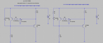
However you can use error correction. There may be capacitance variation and so on but even if the capacitance is off by 10% you still get 1/10 of the output capacitance. The 2.2k resistor curbs reactance at RF. R5 = R1. By increasing R5 you can get a complete null at the corner, resulting in a parallel resonance at 150KHz, if you like. R6 controls the series resonance at 20MHz.
Because the error correction capacitances track, the THD of the error signal itself should be lower as well. This effect applies even if local parasitics prevent a null. If you don't want to use the extra transistor, you can use a cap, but the dynamic null won't be so good.
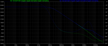
Here is the Zout of the standard ANF CCS and an EC/PFB CCS. Red trace is the right circuit.
I've also plotted Zcb showing that Early affect shunts output resistance causing the vast majority of output conductance. Notice that because the EC transistor is not turned on, it doesn't correct for Early effect; but if it were, output resistance could be much greater depending on matching.
Next plot is the PSRR. R9 cancels PSRR. This resistor can only be approximated unless you have a detailed way of calculating it. A very basic estimation is V(R2)*(R5+R1)*31.5.
So, for what circuits is there any point in going this far? It may help for a very sensitive VAS node in an opamp or triple EF. It may also help with nodes sensitive to nonlinear capacitance, causing distortion.
However you can use error correction. There may be capacitance variation and so on but even if the capacitance is off by 10% you still get 1/10 of the output capacitance. The 2.2k resistor curbs reactance at RF. R5 = R1. By increasing R5 you can get a complete null at the corner, resulting in a parallel resonance at 150KHz, if you like. R6 controls the series resonance at 20MHz.
Because the error correction capacitances track, the THD of the error signal itself should be lower as well. This effect applies even if local parasitics prevent a null. If you don't want to use the extra transistor, you can use a cap, but the dynamic null won't be so good.
Here is the Zout of the standard ANF CCS and an EC/PFB CCS. Red trace is the right circuit.
I've also plotted Zcb showing that Early affect shunts output resistance causing the vast majority of output conductance. Notice that because the EC transistor is not turned on, it doesn't correct for Early effect; but if it were, output resistance could be much greater depending on matching.
Next plot is the PSRR. R9 cancels PSRR. This resistor can only be approximated unless you have a detailed way of calculating it. A very basic estimation is V(R2)*(R5+R1)*31.5.
So, for what circuits is there any point in going this far? It may help for a very sensitive VAS node in an opamp or triple EF. It may also help with nodes sensitive to nonlinear capacitance, causing distortion.
Attachments
Last edited:
I don't consider that symmetry in the +ve and -ve half cycles matters.
In audio signals the +ve and -ve half cycles are not symmetrical.
What matters is the current flow in the +ve half cycle balancing the return current from the speaker and then the -ve half cycle balancing the return current from the speaker. It's these two (alternate half cycle) routes that require low loop area to minimise the radiation.
The current supplied by the amplifier to the load comes back as the return current from the load. There will be some stored and time smeared return currents that do not match the phase of the supply current. Is that what you are referring to?
I would expect that as long as the return current is not an exact copy of the supply current (due to this energy storage in the speaker) we can do nothing to improve the balancing of the flow and return currents.
We can only rely on attenuation measures to minimise the effect of the unbalance on other parts of the circuit. Separation and shielding come to mind.
Hi Andrew,
Ever since I read Cherry's paper long ago I have been concerned about the "half-wave rectified" high currents flowing in the output stage. The two main issues are to keep the loop area small and to electrically or magnetically sum these two currents/fields to a linear field representing the audio signal as close to their physical origin as possible.
One thing this means is that in output stages with multiple output pairs, the NPN and PNP devices should be interleaved, rather than grouped together by sex.
A second thing is that good bypassing sould be provided right at the rails on the board to provide a local low-resistance, low-inductance path to allow local summing of the currents to a linear one. This could even involve a local rail-rail X capacitor.
Note that this implies that some small resistance in the rail lines back to the supply is not necessarily a bad thing, and that the use of very heavy lines, as is often done, may be a well-intensioned but misguided approach.
A third thing, as we all know, is to twist the pos and neg rail wires together on their route back to the power supply, so that the magnetic fields of the two rails sum to a linear field.
There has been some disagreement as to whether the ground return back to the supply should be twisted together with the rail lines, or whether it makes a difference.
Here is an interesting idea, if not controversial. Since some resistance in the rail lines back to the supply is OK, and perhaps desirable, consider using a shielded twisted pair to take both rail lines and the ground back to the supply. Even 20 AWG microphone cable, at 33 mohm/ft, would probably be OK for this short route, even for transients of 10's of amps. The smaller wire allows for a much tighter twist, and shielding that line would seem not to do any harm and maybe some good. Note that a good copper-braided shield has a much higher effective AWG.
Cheers,
Bob
I'm aware the ANF CCS is good. My question was whether using more than just one stabilizing component had any beneficial effect on output impedance.
Compensation if well executed, by, for example, shunt capacitance across the collector-base of the control BJT, should not have any major impact on loop gain in the audio band. At this stage, however, I am not certain that the ANF current source needs its loop gain curtailed at all.
Last edited:
Bob, this is a 'real life' effect that I simulated in Jurassic times with my own DOS linear circuit analysis package.A second thing is that good bypassing sould be provided right at the rails on the board to provide a local low-resistance, low-inductance path to allow local summing of the currents to a linear one. This could even involve a local rail-rail X capacitor.
Note that this implies that some small resistance in the rail lines back to the supply is not necessarily a bad thing, and that the use of very heavy lines, as is often done, may be a well-intensioned but misguided approach.
It was one of those 'Ah ha!' moments when dem evil sims actually explained something you have been struggling with in 'real life'. This year, I moved into the 21st century and started using LTspice but haven't extended any of my naive models to include this.
FWIW ..
- the 'small resistance' can be provide in series with the PS lines but is better provided as resistance in series with VERY local decoupling caps
- physically small electrolytics have just the right amount of ESR to do this
- rail to rail caps help THD20k but do little for stability
- local rail to 'dirty earth' electrolytics help both THD20k & stability
- caveats about these electrolytics AT the output stage cos they get hot
My first hint was Cherry's A New Distortion Mechanism in Class B Amplifiers You don't have to go to his lengths to get substantial advantage. A few judiciously placed electrolytics will do. There is usually enough inductance in the PS leads cos the distance to the big caps.
____________
On twisting / layout etc ... it helps to think of
'the +/- rails, the o/p devices, other stuff hung on the o/p' as ONE of a pair of leads to the speaker from the big PS caps. The other lead is the speaker return to the same caps.
To minimize mutual coupling, radiation etc. it's this pair of leads that need to be twisted, area within minimized, bla bla.
Ground planes etc only obfuscate the issue.
A third thing, as we all know, is to twist the pos and neg rail wires together on their route back to the power supply, so that the magnetic fields of the two rails sum to a linear field.
Since the positive and negative wires will never conduct power at the same time, wouldnt it be best to twist them around the ground?
Since the positive and negative wires will never conduct power at the same time, wouldnt it be best to twist them around the ground?
I think Douglas Self found that this makes things
worse. He suggested to not includes the common in the twist.
I think Douglas Self found that this makes things
worse. He suggested to not includes the common in the twist.
So how does any current except bias current get canceled?
The other two currents are on at different times.
So how does any current except bias current get canceled?
The other two currents are on at different times.
I have seen this argument but how is a twisted pair working:
Let suppose we have two twists A and B following and let's suppose they are circles. If the current in top part of the circle is different from the current of the bottom part of the same circle, they will anyway generate a resulting field. The resulting field of the B twist will be opposite in direction to the one of A. Both will add vectorially at any given time and cancel in part. This will happen even if the currents are different in part of the same circle.
I think Douglas Self found that this makes things
worse. He suggested to not includes the common in the twist.
Hi davada,
I seem to remember him being one who suggested not including the ground in the twist, but I don't recall if he made a scientific explanation for it or came to that conclusion experimentally. I do not know the technical argument for one way vs the other. I'll have to go back and look in Self'd book to see what his reasoning was and how big a difference it made whether the ground was included or not.
The only thing I am sure of is that the plus and minus want to be twisted together to create a linear field, since the sum of the currents in the + and - rails is linear. There also may be a difference one way or the other due to geometry when the ground is included. It could be part of the twist, which might somehow disturb the proper summation of the fields from the rails, or the geometry might be different if the rails are twisted together and enclosed in a ground shield.
Based on geometry arguments, one might argue for the use of star-quad microphone cable in the arrangement I suggested.
Cheers,
Bob
triax
but it gets silly worrying about "the best" cable configuration when it can be physically located many 10s x conductor center spacing distances from your sensitive electronics over most of its length
then you can just bring in the twisted PS/gnd return bundle at 90 degrees to your pcb trace loops, right at the output
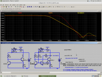
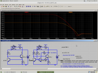
The A & R Cambridge (Arcam) scheme shown here
http://www.diyaudio.com/forums/soli...lls-power-amplifier-book-352.html#post3525147
can be further improved by introducing a zero in the loop gain characteristic in the region of unity gain frequency. This is done by connecting a small resistor (~10R) in series with the capacitor shunting the collector-emitter of the control transistor in the ANF current source.
Phase margin increases from 83 degrees without the series resistor (green trace) to 122 degrees with the series resistor in situ (blue trace).
Attachments
Hi davada,
I seem to remember him being one who suggested not including the ground in the twist, but I don't recall if he made a scientific explanation for it or came to that conclusion experimentally. I do not know the technical argument for one way vs the other. I'll have to go back and look in Self'd book to see what his reasoning was and how big a difference it made whether the ground was included or not.
The only thing I am sure of is that the plus and minus want to be twisted together to create a linear field, since the sum of the currents in the + and - rails is linear. There also may be a difference one way or the other due to geometry when the ground is included. It could be part of the twist, which might somehow disturb the proper summation of the fields from the rails, or the geometry might be different if the rails are twisted together and enclosed in a ground shield.
Based on geometry arguments, one might argue for the use of star-quad microphone cable in the arrangement I suggested.
Cheers,
Bob
Hi Bob,
Mine is the third addition. It's been years since I read the book and I don't remember all the details. I did get the sense of 'this is the theory lets put it to the test' kind of approach. The results were from measurement with out a great deal of explanation.
Much of the book is in instructional form more like a recipe for good amplifier design practices. I prefer something more technical rather than a collection of what one could find in app notes. I rather enjoyed your book more.
An explanation of the physics in graphical form would have been nice. Clear understanding is worth much more than a 'do it this way' kind of presentation.
Cheers,
- Home
- Amplifiers
- Solid State
- Bob Cordell's Power amplifier book