I didn't question your numbers for artifacts. I specifically quoted your line about humans. I doubt process management has much relevance to that. And let's avoid hand waving arguments.
Nixie said:I doubt process management has much relevance to that.
Then, by all means, do not take such classes.
Because the numbers have been the standard, taught in process management classes at any mechanical engineering faculty at any university around the world for many decades.
Oh dear, again guilty of spreading artifacts and hand waving.
You can easily settle this by showing some references to peer reviewed research that supports your claim that humans perform optimally at 90% of their maximum continuous output.
www.tpmonline.com/articles_on_total_productive_maintenance/management/deming14steps.htm
There've probably been hundreds of books written on lean manufacturing.
Also see: Joseph Juran, the Pareto principle, and the 90-10 or 90/10 law.
For human behaviour, both the 90/10 and 80/20 rules are quite interesting.
There've probably been hundreds of books written on lean manufacturing.
Also see: Joseph Juran, the Pareto principle, and the 90-10 or 90/10 law.
For human behaviour, both the 90/10 and 80/20 rules are quite interesting.
What voltage (open circuit) is the transformer giving?lumanauw said:If I want to know the transformer capability of delivering to 4ohm load, what is the R dummy size (ohm) that must be used for the test like you proposed?
What diameter of wire is used for the secondaries?
A transformer is rated into a resistive load not into a capacitor input filter.
let's give some numbers to lumanauw's experiment, let's say he wanted to test a 500va transf. with 60 volts unloaded secondary.
computing for power with a 4ohm load, power drawn out will be (60x60)/4 = 900va (actuall will be less due to copper losses.) and so here we see that the transformer will be severely overloaded.
transformers can be overloaded intermintently.
still you may try and see how fast the transformer heats up but proceed with extreme caution...
BTW I want to ask, if there's disagreement between PSUD2 and LTSPICE, which one do I trust? Often times I'll get a few % difference.
Hello,
I read this tread from beginning to the end. Great info. If one would like to summarize this tread, a schematic at the end would be great, which include all mentioned. My interest - question is about bypass caps. Is there any calculation for these caps? I will try to summarize what I plan to do, so maybe that will include all mentioned in this tread. So here it is:
Dual secondary torroid 2x60V 1000VA
Dual rectifier bridges 600V 35A (per Mr. Pass dual bridges are OK)
4 x 59,000uF 75V
4x 0.22 ohm between two banks of caps
Bypass metallized polypropylene 1-3 uF and 0.1uF on each cap
Bypass metallized polypropylene 1-3 uF between + and - rails most likely 400V will cover any situation.
Caps located closest possible to the output rails.
I do not have any program that will output schematic, but I could do it in the Illustrator. I will wait for the comments and incorporate them in the schematic.
Hi,
75V caps on an 84Vdc supply that could exceed 90Vdc when mains is running high.
Have a re-think.
75V caps on an 84Vdc supply that could exceed 90Vdc when mains is running high.
Have a re-think.
AR2 said:Hello,
I read this tread from beginning to the end. Great info. If one would like to summarize this tread, a schematic at the end would be great, which include all mentioned. My interest - question is about bypass caps. Is there any calculation for these caps? I will try to summarize what I plan to do, so maybe that will include all mentioned in this tread. So here it is:
Dual secondary torroid 2x60V 1000VA
Dual rectifier bridges 600V 35A (per Mr. Pass dual bridges are OK)
4 x 59,000uF 75V
4x 0.22 ohm between two banks of caps
Bypass metallized polypropylene 1-3 uF and 0.1uF on each cap
Bypass metallized polypropylene 1-3 uF between + and - rails most likely 400V will cover any situation.
Caps located closest possible to the output rails.
I do not have any program that will output schematic, but I could do it in the Illustrator. I will wait for the comments and incorporate them in the schematic.
So, for each rail, we proceed through a 0.22 ohm resistor to a first 59,000 uF cap, then through a second 0.22 ohm resistor to a second 59,000 uF cap, then on to the load?
Why is the first 0.22 ohm resistor being used?
A 60V secondary into a full-wave bridge will produce about 84V no-load, which is too much for the 75V caps. Or did I interpret your arrangement wrong and you have a pair of 75V, 59,000 uF caps in series (but that would not seem consistent with your statements about the 0.22 ohm resistors)?
The 0.1 uF capacitor may want to be a ceramic so as to avoid the winding inductance of a film capacitor.
Bob
I am sorry, I made mistake. Torroids are 2x45V and I count them to produce around 60V after rectifiers and caps. Same thing with 0.22 ohms - it is 2 x 0.22 ohms between two banks of big caps. It was too early when I typed it in.
AR2 said:I am sorry, I made mistake. Torroids are 2x45V and I count them to produce around 60V after rectifiers and caps. Same thing with 0.22 ohms - it is 2 x 0.22 ohms between two banks of big caps. It was too early when I typed it in.
ya shall sleep sometimes.........😉
in your boots (and No. is?) ....you can place right across last caps no less than 1Uf ;
if needed,little ones (100n) place ditto on pcbs ,where you probably also plan some local decoupling,with smaller elkos .
Adding turns to toroids
Here's a funny story that really happened to me about six months ago. I needed to add some turns to a toroid power transformer - about 30 turns to each side of the center tap. So I looked in my drawer of enameled wire and found some wire of the appropriate gauge - I think it was maybe 18. I proceeded to wind all the turns and then tested the transformer. It got VERY hot VERY quickly!! What was wrong? This nice-looking wire that I used appeared to be enameled wire (as you know, enamel insulation comes in many different colors and shades of brown), but it actually was bare copper wire! How stupid of me!
Cheers,
Bob
Re: Adding turns to toroids
shoulda' used nichrome -- would've heated even faster.
Bob Cordell said:Here's a funny story that really happened to me about six months ago. I needed to add some turns to a toroid power transformer - about 30 turns to each side of the center tap. So I looked in my drawer of enameled wire and found some wire of the appropriate gauge - I think it was maybe 18. I proceeded to wind all the turns and then tested the transformer. It got VERY hot VERY quickly!! What was wrong? This nice-looking wire that I used appeared to be enameled wire (as you know, enamel insulation comes in many different colors and shades of brown), but it actually was bare copper wire! How stupid of me!
Cheers,
Bob
shoulda' used nichrome -- would've heated even faster.
AR2 said:Here is the drawing of the power supply as I promissed with your input. Please note correctios if needed.
Thank you
AR2
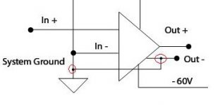
dunno to whom this post is addressed.......but looks fine for me ;
just one thingie - why you grounded minus output?
I think he's just showing signal ground that way.Zen Mod said:why you grounded minus output?
Nixie said:
I think he's just showing signal ground that way.
I'm not sure ;
I know what he's building
Zen Mod said:
dunno to whom this post is addressed.......but looks fine for me ;
just one thingie - why you grounded minus output?
It is probbaly lost in compression - connections are marked with small black dot. That was just wires crossing each other without connection. I will correct and make bigger dots, so if someone looking into it ... wouldn't make same conclusion as you are.
AR2 said:
It is probbaly lost in compression - connections are marked with small black dot. That was just wires crossing each other without connection. I will correct and make bigger dots, so if someone looking into it ... wouldn't make same conclusion as you are.
more milling ,less drawing......seems as best recipe for few days

edit:
I edited just two red circles.....nothing more 😉
Attachments
- Status
- Not open for further replies.
- Home
- Amplifiers
- Solid State
- Bob Cordell Interview: Power Supplies