Hi lumanauw,
Agree. As pointed out earlier, all stages in an amp should be designed as linear as possible, no matter how. But indeed the output stage is the hardest part. Especially biased in class-AB.
But long time ago, inspired by Hiraga, I build an (class-A) amp with an output stage acting as a current source for stability and bandwidth reasons. Did put around global feedback to make is acting as a voltage source. Actually that was a nice sounding amp with a harmonic profile that drooped off rather quickly.
😉
PMA said:Hi Andy,
I wonder if you could add a frequency dependent loopgain into your simulations. It might bring interesting results.
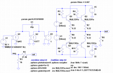
Pavel made this request, so I did a sim mostly as described in this post. The exception is that I used a 4 Ohm load instead of 6 Ohms to get a higher simulated distortion while still using "best design practice" (optimum bias) in the output stage. The schematic of the simulated circuit is shown below.
There are 2+2 BJTs in the output stage, with 0.22 Ohm resistors. Bias is adjusted to Self's optimum of 107 mA per device with this RE value. Base resistors of 10 Ohm are present (same as Leach amp) and supplies are +/- 55V (about the same as Leach).
The open-loop amplifier is an idealized integrator with variable time constant and zero output impedance. That time constant is varied to adjust the unity loop gain frequency as described in the post I referenced above. This was done by changing input stage transconductance.
The output signal was set to 4V peak, corresponding to 1A peak. Crossover distortion decreases as the output voltage goes above and below this value. THD of the output stage by itself was just slightly less than 0.1 percent at this output level without feedback.
The output stage distortion was simulated by itself (zero feedback case), as it's not possible to have zero feedback with an integrator in the feedback loop. All other data points had the integrator in the loop.
Attachments
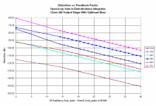
Here is the plot of distortion vs. feedback. A little explanation is in order here.
The x-axis data is feedback factor in dB, or 20*log(|(1+AB|). So the zero dB point is with no feedback. The frequency at which the feedback factor is evaluated is 20 kHz, to correspond to the convention Self uses to distinguish high-feedback and low-feedback designs. There is a jump at the lower feedback values, where the first feedback factor is 0 dB (no feedback at all), and the second is about 14 dB. This 14 dB number corresponds to an amp with heavy overcompensation such that its closed-loop bandwidth without input filter would be only 100 kHz. The maximum feedback factor of 40 dB at 20 kHz corresponds to an aggressive high-feedback design such as Bob's EC amp, with a closed-loop bandwidth without input filter of about 2 MHz.
Because the x-axis data jumps from 0 dB to 14 dB, I've put markers on the plot lines to show where the simulated data was actually taken. There were 21 simulation points.
One thing that can be seen is that when you go from zero feedback to very low feedback, the relative harmonic levels of the 7th and 4th "trade places" due to the feedback being able to reduce lower-order harmonics more than the higher-order ones. But as you go from low feedback to high feedback, the relative levels are approximately preserved, and they are all reduced in level as feedback increases. There is no evidence of feedback increasing distortion as it is increased.
Edit: Oops, I forgot to mention that the distortion was simulated at 5 kHz.
Attachments
Hi Andy,
looking forward the plots impatiently 😉
By the time I also made some sims, hereabove.
errata: they have just appeared, thanks! 😀
looking forward the plots impatiently 😉
By the time I also made some sims, hereabove.
errata: they have just appeared, thanks! 😀
PMA said:Hi Andy,
looking forward the plots impatiently 😉
By the time I also made some sims, hereabove.
errata: they have just appeared, thanks! 😀
Looks like we both posted at the same time 🙂.
andy_c said:
But as you go from low feedback to high feedback, the relative levels are approximately preserved, and they are all reduced in level as feedback increases. There is no evidence of feedback increasing distortion as it is increased.
I guess that increasing distortion with feedback increased is just a myth.
Also, we can see that it makes no sense to use very small amount of feedback.
Nice work Andy 🙂
Does that imply on the other hand you can make it as high as possible?
PMA said:Also, we can see that it makes no sense to use very small amount of feedback.
Does that imply on the other hand you can make it as high as possible?
Let me remind you of my 'story' as well.
About 40 years ago I started to work at Ampex Corp. and in about 6 months I would be working in the audio department. The first thing was that I an access to parts and materials to try things, and I decided to make my very first unique power amp. At this time, I listened in mono mostly (many of us did then) and I had 1 Klipshorn to listen through. The K-horn proudly has a sensitivity of 104dB/watt. Therefore, you only need a 10W amplifier to listen to it.
I had worked with triode amplifiers and knew that they were good, but my ultralinear Dyna MK 3 amplifier had a certain 'signature'. Perhaps I could make a better amplifier with the latest solid state devices that would match or beat the triode amplifier that I knew sounded pretty good.
My first amp was push pull throughout, but with NO differential pairs. I had not invented the complementary differential yet. That would be gen 2 of this amp, in next year.
I chose 1/2 A bias, because that was the beta peak of the output devices. 1 ohm emitter resistors, because they met Bob Cordell's thermal stability criterion, and 40 dB of negative feedback, because I could.
My measured distortion at 1W (104dB remember) and below was LESS than 0.005% IM distortion! Wow, a new record, or at least as good as anyone else on the planet.
My worries were over! I had the virtually perfect K-horn power amp!
Of course, I checked other things, such as the ORDER of the harmonic distortion. Almost pure 3'rd, when it was measurable up to full output of about 15W, a bandwidth of about 100KHz, and a damping factor of 30. Also, I made it UNCONDITIONALLY stable with virtually any value of cap load, and it had NO protection circuitry, or output coil.
It actually did sound better than the Dyna MK3 (with Genelex KT88 output devices) for some reason, as well.
I was convinced that I had done it. I had replaced the tube amp!
Then, Marantz introduced their power amp. It was about 60W per channel, unmeasureable distortion at 1W, cute package, and its base seemed to sound better than my amp. I bought one, and used it for awhile. However, I found that I would get 'listener fatigue' listening to it. I went back to my prototype and the 'listening fatigue' disappeared, and even with the Dyna MK3, there was no 'listener fatigue'.
Something was wrong, but I did not know what it was, because our best test measurements at the time could not sort out a problem.
About the same time, I directly compared my prototype solid state amp with a triode vacuum tube amp made by a company called 'Radiocraftsman'. Interestingly enough, the damping factor of this amp was about 30, the bandwidth was about 100KHz, and the IM distortion was virtually unmeasurable at 1W or less, rising monotonically to .1% at 10W with mostly 3rd harmonic distortion similar to my solid state amp.
We decided to run a listening comparison, between the amps, matching the outputs to less than .1dB (we didn't need Lipshitz to tell us this) and making an A-B comparison, I PREFERRED the tube power amp! WHY? Everything was just about the same, but the triode sounded better. The ONLY difference that I could judge at the time was that I required 40dB of negative feedback to do what the tube amp did with 20dB. This result, coupled with Matti Otala's paper 2 years later, got me to think that feedback was problematic. The rest is the trials and tribulations of almost 40 years.
PMA said:I guess that increasing distortion with feedback increased is just a myth.
The increasing distortion with increasing feedback does seem to occur when the open-loop distortion is dominated by the second harmonic. One of Bob's earlier sims in this thread seems to verify Baxandall's results in that regard. But that seems to be a very special case. I think this special case result has been generalized incorrectly, most notably by Cheever. Then people have taken Cheever's results and waved them around in various online forums, etc. Then it spreads.
Also, we can see that it makes no sense to use very small amount of feedback.
Pavel, I'm not going to touch that one!

john curl said:It is underbiased because it is in class A-B too much of the time. I started with .5A in 1967. I have tried to go up from there with my later designs. Of course, only my BEST efforts. I do have to allow for cheaper, more compromised amps, that cost a lot less. I can only do the best that I can with those amps, and make a smooth transition.
Now let's see what negative feedback does with 50ma idle current? That is pretty typical.
Hi John,
Don't get me wrong, I like high-biased amplifiers as well. And certainly a "typical" 50-80 mA Class AB bias for a BJT amplifier has always been a concern for me, especially given the possibility that thermal bias mis-tracking may occasionally drive that to a much smaller value.
Bear in mind that my 50 watt MOSFET amplifier with error correction was just a prototype demonstrator for the AES paper. That's why it was a relatively small amplifier at 50 watts and using only one output pair. Biased at 150 mA, it still had a quite higher bias current and "Class-A" region than many BJT designs at that power level at the time.
Moreover, if I had done that design with a huge idle bias, the point that I was trying to make about the use of error correction would have been seriously blunted. I was really trying to show how such extremely good performance could be achieved with a "reasonable" amount of bias current. This was not out of the ballpark of the kind of bias current that was being used in the Hafler MOSFET amps, for example.
In 1983 I built a 200 watt prototype of the MOSFET amplifier with error correction. It used five output pairs, each biased at about 100 mA, for a total idle bias of about 500 mA. It worked very well. So one could say that it had a larger Class-A region like you prefer, although not as big as the nice huge class-A region that you have in the JC-1.
Cheers,
Bob
john curl said:PMA, you answered your own question, you have the output stage OUTSIDE the feedback loop! Tell that to Bob Cordell and please remember, that is WHY you are NOT tempted to starve your output stage, like Bob Cordell does: 😀
John,
This is the kind of comment that you occasionally make that poisons a thread.
I do not starve my output stage and I am not tempted to do so.
You should leave these kinds of unfair comments to politicians in debates.
Bob
Feedback will not help for underbiased output stage.
Can EC help underbiased output stage?
Is EC the same or different than Feedback?
Can EC help underbiased output stage?
Is EC the same or different than Feedback?
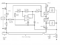
I don't understand much of this, but EC seems different than feedback. It has additional "energy" to fix things, that is not coming from the previous stage (it has it's own energy source).
In this example, an opamp (It only compares 1:1, not making any voltage gain) is powered +/-15V floating (bootstrapped) towards the output node. This way, opamp can give more positive or more negative signal than the previous stage can, just to fix the output stage only.
In this example, an opamp (It only compares 1:1, not making any voltage gain) is powered +/-15V floating (bootstrapped) towards the output node. This way, opamp can give more positive or more negative signal than the previous stage can, just to fix the output stage only.
Attachments
lumanauw said:Feedback will not help for underbiased output stage.
Feedback reduces distortion even for underbiased output stage (less than optimal Iq). Of course it does not mean that feedback makes a good amplifier from that with underbiased output stage.
P.S.: here is the image showing that feedback reduces distortion even for no-bias output stage. Pure crossover distortion. OPA134.
Attachments

'Starved', is a relative thing, Bob. Your amps are 'starved' compared to my best ones, but my cheaper ones may have about the same bias as your first effort. Is 'current challenged' OK? 😀
Of course, feedback reduces MEASURED distortion. Why do you think that Charles Hansen does not use global negative feedback? Any ideas? Hint: Any listening experiences?
andy_c said:There is no evidence of feedback increasing distortion as it is increased.
PMA said:I guess that increasing distortion with feedback increased is just a myth.
It is correct that there is no visible evidence of increasing distortion in Andy's plots (very good work, Andy!), because this is dependent on the initial distortion and the degree of NFB. As Baxandall's work showed, if one starts off with enough non-linearity the evidence shows up soon enough. In Andy's case most of the amplification is perfectly linear, thus no evidence in his plots.
But one will have a hard time, PMA, to call increased distortion with NFB a myth per se, because then you will have to indicate a flaw in the maths - it is there! I think this is the point, that qualitive statements (and what a number of those we have had here!) lead to more misrepresentation than information (not picking on you, PMA - you probably made your remark in the context of practical use). In the plots I showed in my post #1274 some "come-back" can be observed, though that may not have been only because of NFB.
I do not quite agree that early stages do not contribute significantly to distortion. It is true that it is basically a power stage problem, but then that is also where one usually has most NFB - compare the e-follower and full cp.
There is also occasionally a disregard for phase shift. In that sense it is not OK to have "enough" NFB at 20KHz, coming from an op-amp dipping from 500 Hz with goodness how much fb at say 100 Hz. A look at the phase angle will explain why some designs are not too stable at high frequencies.
Lastly, I have found more distortion from some high Ic final stages (gm doubling) than from the right amount of Ic(q). Andy, you may try to simulate without the power transistor Re's [at same Ic(q)] and compare, especially high order harmonics (I mean up to 13th)? I found a significant decrease in high order harmonic content.
May I ask again that members kindly state with their plots at what % of maximum output power those were taken. There will be a difference between 50W and 1W!
Johan Potgieter said:I do not quite agree that early stages do not contribute significantly to distortion. It is true that it is basically a power stage problem, but then that is also where one usually has most NFB - compare the e-follower and full cp.
Hi Johan,
I don't think anybody was claiming that the early stages don't contribute significantly. People were observing that the way in which feedback affects distortion depends a lot on the specific nature of the distortion without feedback. Then Bob got the idea of looking at how feedback affects crossover distortion. If one were to introduce nonlinearity elsewhere in the simulation, it would confuse things. So it's just a way of looking at one thing at a time, not a claim that other things don't matter. I just extended Bob's idea to include frequency compensation effects. I actually thought the integrator would make things much worse, but was surprised that wasn't the case.
Johan Potgieter said:Lastly, I have found more distortion from some high Ic final stages (gm doubling) than from the right amount of Ic(q). Andy, you may try to simulate without the power transistor Re's [at same Ic(q)] and compare, especially high order harmonics (I mean up to 13th)? I found a significant decrease in high order harmonic content.
I'm not quite sure what you're asking. If RE is removed, then the stage will be underbiased if the 107 mA current is kept constant. Are you saying that the underbiased condition decreases high order harmonics? Or just that you're interested in looking at data for the underbiased condition? Or something else?
Thanks Andy.
Maybe symantics here - I did misunderstand in the first instance and appreciate the explanation.
Regarding the series emitter resistance (external), I meant that I found a difference with and without the (say) 0.22 ohm compensating resistors in the emitter circuit, output transistors biased at the same collector current. In my case I used full complimentary pairs, so the resistor is actually in series with the equivalent "emitter" - the usual place for such topologies.
I unfortunately do not have a working scanner at this time; I can go do this elsewhere and post here if you are interested.
- Home
- Amplifiers
- Solid State
- Bob Cordell Interview: Negative Feedback