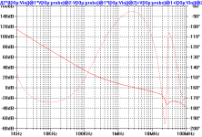
janneman said:I'd also say that the EC is much more inductive, which points to a lower ol bandwidth, no?
Jan Didden
Probably very flat and high OLG of symasym?
http://web.telecom.cz/macura/bode1.gif
PMA said:
I am somewhat confused here.
The OL bode shows about 30 deg. of phase lag at 10 KHz, fitting the x-y plot. Yet, the closed loop response should be more or less near the 1/beta plot at 10 KHz. Phase lag for this case is not plotted but it can be guessed to be very low since the corner is beyond 1 MHz, and the forward path deviation gets attenuated by the same OL/CL ratio (50 dB).
Rodolfo
Hi Rodolfo,
Just read your post#611.
You apologise, but please allow me to do so too, for now I follow your intended meaning. We all use words and expressions differently.
Hi PMA,
Your scope pics are good.
First two show good balance between output halves.
Lower one some gain asymmetry starting to show.
I do not know what the EC is as I have not visited diyAudio for several years and am following only two SS threads.
However I echo Jan's comment because the second pic shows open loop gain is bandwidth compromised and causing damping phase shift, even though the closed loop specification is probably AF flat.
Cheers .......... Graham.
estuart said:
Hi Mike,
One of the two:
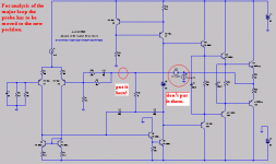
1. global (major) feedback loop and erroneous results. In this case the top your R10 (my R1) should be be connected directly to the output, instead of tied behind (left) to the loop probe.
or:
2. correct results, but targeted at a different loop, but then, what kind of loop, inner, Miller?
Please, explain (and check if we are looking at same diagram).
btw I couldn't see any load resistor (8Ohm), why?
Cheers, I'll be back in 1 hour.
Connection of probe between resistor and output:
To determine the sum of major loop and minor loop contributions with respect to the output stage; i.e. establish the total loop gain enjoyed by the output stage.
Just how and why would you expect an 8ohm resistor to affect your loop gain response?🙄
mikeks said:
Hi Mike,
Maybe I overlooked a third possibility, that is, we fully agree 🙂
however...... the picture below might put things in a different light.
Please, have a look.
Attachments
estuart said:
Hi Bob,
In other words, sound efforts to reduce thd by means of this technique (TPC) are limited to moderate results.
Cheers,
estuart said:
Hi Bob,
In other words, sound efforts to reduce thd by means of this technique (TPC) are limited to moderate results.
Cheers,
Yes, but one might ask what is a reasonable expectation for moderate. I have at times been tempted to use TPC in audio power amps, but have never built one with it, so I'll apologize ahead of time and be a bit speculative here.
In my opinion, the best you can safely do is to approximate a 9 dB/0ctave rolloff (Bode actually proposed 10 and change, but I think that left him with only a thirty degree phase margin).
Let's say that your amplifier can have its loop closed for a gain crossover of 1 MHz with adequate phase margin going through 1 MHz at a 9 dB/octave slope. This is not easy, because you are only starting with a 45 degree margin before you consider excess phase of the output stage. Again, this is an upper limit on what would be safe. There are two decades less an octave separating 20 kHz from 1 MHz. The 9 dB/octave slope, or 30 dB/decade, provides an "advantage" at 20 kHz of about 3 dB per octave or 10 dB per decade of separation. Therefore, we have 20 dB less 3 dB, or 17 dB best case advantage, in my opinion.
This is nothing to sneeze at, but it is an agressive best case in my opinion. For better phase margin, we might have to make do with a 640 kHz gain crossover. For better transient response and to account for approximation error to the 9 dB/octave slope, we might want to back off the target slope to 8 dB/octave. This gives us a net gain of 2 dB per octave of separation from 20 kHz to the gain crossover frequency. We now have only 5 octaves for a net advantage of 10 dB.
But we are not finished. We have only looked at NFB improvement at 20 kHz. The nasty stuff of the harmonics at 40, 60, 80, 120 ... kHz will be reduced by a lot less, since their separation from the gain crossover frequency is a lot less.
I hope I have not waived my hands too much here, much less make a horrid mistake in my numbers (which Mike will be sure to catch 🙂).
Bob
estuart said:
.......we fully agree.......
No.
Now you're determining major loop transmission, which is all that is available to the input stage, but not the last two stages of the amplifier.
This is key!
Bob Cordell said:.....I have at times been tempted to use TPC..........the best you can safely do is to approximate a 9 dB/0ctave rolloff (Bode actually proposed 10 and change, but I think that left him with only a thirty degree phase margin).
You appear to forget that a DPC necessarily generates an LHP zero to cancel one of the poles....
Hi Graham
the EC AB1 (or PM-AB1) is this amp:
http://web.telecom.cz/macura/pm_ab_er1.gif
(hinted by NP drawing few years ago)
Hi Rodolfo,
it is again only simulation, and as you can tell from oscillograms and previous simulations of reverse drive before, simulation is only the 1st approach, then it is the real life to be tuned. Simulation is a good tool, but cannot substitute building circuits. Sometimes the simulation is quite misleading.
PMA said:..... Simulation is a good tool, but cannot substitute building circuits. Sometimes the simulation is quite misleading.
I cannot agree more in this respect. In fact I find rather amusing to quote simulation results in the ppm range. I am afraid too much faith is put on device models, and while it can be argued simulations nonetheless allow at least for comparative tests with the same devices, I am afraid still there are higher order non included effects whose infuence is being ignored yet may be significant at this resolution level.
Rodolfo
Definiation
Hi Mike,
That's right, it's all a matter of definition. But still we disagree with the merits of 'my invention'. Actually it's not mine, alas.
Cheers,
mikeks said:
Now you're determining major loop transmission, which is all that is available to the input stage, but not the last two stages of the amplifier.
This is key!
Hi Mike,
That's right, it's all a matter of definition. But still we disagree with the merits of 'my invention'. Actually it's not mine, alas.
Cheers,
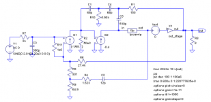
Mike, when you have the loop gain probe right after the output stage in that configuration, I'm not so sure it has the physical interpretation you're assuming it does. I tried the two-pole comp with a third capacitor and added resistor. Here is a plot of the overall loop gain of the amplifier. Notice that at 20 kHz, it is 60 dB.
Attachments
Now I move the loop gain probe so it's right at the output of the output stage, before the resistive pickoff that goes back to the VAS. This mod gave me a distortion improvement at 20 kHz of over 2x. Notice in this plot that the loop gain is 50 dB at 20 kHz. Less than the global loop gain? I don't know what this means.
This is the same circuit in both cases, just different loop gain probe positions.
This is the same circuit in both cases, just different loop gain probe positions.
Attachments

mikeks said:Andy, run the sim here.
I saw that but it used a bunch of Zetex models that you apparently put into your standard.bjt. I was too lazy to round them all up 🙂.
Your circuit is different from mine. Mine indicates all loops are stable. Here is the network.
Attachments
mikeks said:Just how and why would you expect an 8ohm resistor to affect your loop gain response?
Hi Mike.
With respect to the major loop, not that much, but as a careful man, I always include the output load.
Concerning the inner loop, there are numerous subtleties, including output loading, that should not be overlooked. For example, a small emitter series resistor in the VAS stage, not shown in your diagram btw, could have decisive effect on stability. See a paper of E.M. Cherry on this subject (lots of matrix algebra, as usual :-( ).
Cheers,
estuart said:
See a paper of E.M. Cherry on this subject.
Cheers,
I saw that examined it and found it to be nonsense, as did Dr Gift and a few others.
Bob Cordell said:I hope I have not waived my hands too much here, much less make a horrid mistake in my numbers (which Mike will be sure to catch 🙂).
ROFL! Here's how I go about designing the thing.
Suppose you have an amp that you've determined, via single-pole comp, can have a unity loop gain frequency of 2 MHz. Of course, for single-pole comp, you'll have a loop gain of 40 dB at 20 kHz. The two-pole comp network has zero on the negative real axis. Let's put that zero at 1/10 the unity loop gain frequency. That means it will degrade the phase margin by 6 degrees (phase lag = -96 degrees at 10x the freq of the zero). A little lead comp can take care of that. In fact, Edmond's trick applied to the two-pole comp allows for just that. So now we have the open-loop zero at 200 kHz. The idealized Bode plot will have 20 dB loop gain here. Below this freq, we'll have 40 dB/dec slope. So at 20 kHz, we'll have 20 dB + 1 dec *40 dB/dec or 60 dB at 20 kHz (like my plots above). Of course, above 200 kHz the two-pole comp is no better than the single-pole. But for 19+20 kHz IM, I would think the two-pole comp would have a 20 dB advantage.
andy_c said:
I saw that but it used a bunch of Zetex models that you apparently put into your standard.bjt. I was too lazy to round them all up 🙂.
Your circuit is different from mine. Mine indicates all loops are stable. Here is the network.
Hi Andy,
With your arrangement The major loop will be double pole while that part of the minor loop enclosing the output stage will have a triple pole roll-off. 😱
andy_c said:
I saw that but it used a bunch of Zetex models that you apparently put into your standard.bjt.
Use any models you want.
- Home
- Amplifiers
- Solid State
- Bob Cordell Interview: Negative Feedback