Hi All,
There is more in this thread than I can note and answer at the moment.
Amplifier delay, when enclosed by a NFB loop, makes the combined output terminal/sensing node inductive in response to external stimuli esp. loudspeaker system generated back-EMF.
This was well known and published decades ago.
Thus the output terminal of an amplifier becomes an input terminal for the closed amplifier system, and delayed NFB control cannot prevent the generation of an error wrt normally amplified input before the NFB loop can establish output terminal control.
The fractional pre-correction error can energise tweeters due to back-EMF from prior energisation of the loudspeaker system at other frequencies when compared to on-going audio input, and this is audible.
The greater the use of global NFB to optimise forward amplitude linearity, the more AUDIO distortion will be introduced due to path delay caused by necessary closed loop stabilisation components impinging upon open loop bandwidth and thus making the loop more inductive at audio frequencies.
I am not trying to make any statements with these circuits.
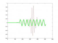
See class-A//AB with more coherent NFB - blue traces
Class-AB without choke or Miller C.dom - fuschia traces
Class-AB with choke and Miller C.dom - black traces
Class-AB without choke, with C.dom - lime traces.
Comparing error due to 10kHz back-EMF sine
Also swept amplitude and phase of error.
Of course all these are simulated, and real life output impedances can never be so low, but this gives an idea of how an output terminal behaves when back-EMF becomes momentarily leading wrt amplifier input.
( Not allowed to attach my test circuit file ! Its a 38kB GIF but over 1000 because it shows 4 circuits. PAH! )
So just attaching the output traces, all made by reverse energising the output terminals via 8 ohm resistors.
The first charts output terminal voltage with 1Vpk sine energisation *starting* at 0V: the second the amplitude and phase of output terminal responses (closed loop) due to sine energisation via 8 ohm output load.
There is more in this thread than I can note and answer at the moment.
Amplifier delay, when enclosed by a NFB loop, makes the combined output terminal/sensing node inductive in response to external stimuli esp. loudspeaker system generated back-EMF.
This was well known and published decades ago.
Thus the output terminal of an amplifier becomes an input terminal for the closed amplifier system, and delayed NFB control cannot prevent the generation of an error wrt normally amplified input before the NFB loop can establish output terminal control.
The fractional pre-correction error can energise tweeters due to back-EMF from prior energisation of the loudspeaker system at other frequencies when compared to on-going audio input, and this is audible.
The greater the use of global NFB to optimise forward amplitude linearity, the more AUDIO distortion will be introduced due to path delay caused by necessary closed loop stabilisation components impinging upon open loop bandwidth and thus making the loop more inductive at audio frequencies.
I am not trying to make any statements with these circuits.
See class-A//AB with more coherent NFB - blue traces
Class-AB without choke or Miller C.dom - fuschia traces
Class-AB with choke and Miller C.dom - black traces
Class-AB without choke, with C.dom - lime traces.
Comparing error due to 10kHz back-EMF sine
Also swept amplitude and phase of error.
Of course all these are simulated, and real life output impedances can never be so low, but this gives an idea of how an output terminal behaves when back-EMF becomes momentarily leading wrt amplifier input.
( Not allowed to attach my test circuit file ! Its a 38kB GIF but over 1000 because it shows 4 circuits. PAH! )
So just attaching the output traces, all made by reverse energising the output terminals via 8 ohm resistors.
The first charts output terminal voltage with 1Vpk sine energisation *starting* at 0V: the second the amplitude and phase of output terminal responses (closed loop) due to sine energisation via 8 ohm output load.
Attachments

We went through this before. You are deliberately using an input signal that is unrealistic (the sine suddenly starts at the max value). If you use an input lpf with a cutt-off freq of say 30 or 40kHz, this effect disappears.
Also I would like to know what that feedback delay value is that ostensibly gives the effects you mention. With band-limited audio signals, not with some some unrealistic ultrasonic input signal.
Jan Didden
Also I would like to know what that feedback delay value is that ostensibly gives the effects you mention. With band-limited audio signals, not with some some unrealistic ultrasonic input signal.
Jan Didden
Yes I was challenged on this before, but I don't believe we ever went 'through' it.
Past attitudes placed burden upon me, so I went away. (If you knew what other problems I still have to deal with in real life - not just my own!!! - maybe you would try to work out what I am attempting to say for yourself.)
!!!!! Do not think that I do not understand what YOU are saying !!!!!
The PROOF comes when you examine a class-AB amplifier with a loudspeaker system load and you subtract a delayed sine (wrt input) from that appearing at the output terminal at some frequency where the load current leads the voltage. This is very time consuming to set up, even more so via simulation, and frankly 'attitude' makes me feel like not wanting to bother.
With leading back-EMF the zero current crossovers in the output stage become load driven instead of input signal driven. Thus there is a time difference in the control necessary when a resistor is being driven, and a loudspeaker is being driven. Also the back-EMF can change phase within an audio waveform cycle, thus tiny 'servo' errors develop in advance of NFB loop generated control.
Of course this is only one of many errors generated at an amp-LS interface.
Graham,
FWIW, I believe you. 😎
The significance of the vector subtraction of reflected back emf off the speaker and unadulterated input at the feedback node is underestimated. There is some evidence in my experience that the subtraction process - viz creation of the error signal - could be done better.
If speakers and amps were designed for current feedback I suspect things would be better.
I am in awe of your understanding of such things, but there MUST be a better way to explain it to avoid the 'attitude' of which you speak.....
Cheers,
Hugh
Hi Hugh,
I agree with your comments too.
As far as explanations go I am more of a 'hands-on' and 'ears-on' guy than a pure maths certificated theoreticist.
Vectors ! LOL. More arrows !
My concern with current feedback is that conventional dynamic loudspeaker systems cannot be adequately damped. Some designers use Zobels within their crossovers, but even here dynamic current flows are out of phase with driver currents, so the (amplifier sensed) loudspeaker system current can be quite different to transducer current.
I personally have not looked for this, but some very sharply tuned crossover circuits (inappropriate design) can affect responses.
Back-EMF tends to be less than drive when a single sinusoid is being studied, but then when the drive changes - as with cymballs and drums, or voice and guitar - does the image blur ???
Most dynamic loudspeaker system currents change during the first couple of cycles at most frequencies.
Driver resonance is shown as an impedance peak (lower current) - but it does not start out that way. It draws almost full voice coil resistance limited current for the first 90 degrees and then falls away over the next couple of cycles.
Similarly crossovers can pass limited current during the first 90 degrees, and then currents can build up to be much greater than expected.
Thus we need to understand how the ouput terminal copes when it is driven wrt input, because class-AB conduction crossovers are related to loading and not (frequency limited) music input.
Above 1kHz many amplifier designs have a reducing damping characteristic with frequency (C.dom impaired open loop bandwidth) that is in quadrature with back-EMF; most multi-driver loudspeaker systems have back-EMF in quadrature with applied voltage close to their crossover frequencies; any wonder that some amp-spkr combinations can sound peaky at high AF because the NFB loop 'controlled' voltage can become phase shifted wrt driver output !
No NFB no problem; but no dynamic control either.
AKSA said:Graham,
FWIW, I believe you. 😎
The significance of the vector subtraction of reflected back emf off the speaker and unadulterated input at the feedback node is underestimated. There is some evidence in my experience that the subtraction process - viz creation of the error signal - could be done better.[snip]Hugh
Well, if that is so, let's see it. This type of process works into the 10's of MHz, so if there is a delay problem, why does it mess up things below 20kHz? If the feedback process can almost nullify 20kHz distortion because the subtract-and-correct works fast enough to take care of harmonics up to 40 or 50kHz, why does it then have a problem with a slow mechanical speaker delaying something many milliseconds? Why it is that you and Graham don't get into this and clear it up for once and for all?
I'm not saying it is impossible, I'm trying to get my head around it but have very little to go on except anecdotal stories.
I've more often tried to reason out things that were thrown up off-hand, only to be accused of having an attitude by those who don't like my reasoning. I think I'll survive yet another case.
Jan Didden
Graham
I agree, that output terminal of an amp looks like an inductor and speaker load can vary, but even the worst case, like inductive output-capacitive load the total phase shift is unlikely to reach 180 degrees.
Ergo the whole phase shift by compensation and load response will not prevent feedback from doing its job.
Graham Maynard said:Hi All,
There is more in this thread than I can note and answer at the moment.
Amplifier delay, when enclosed by a NFB loop, makes the combined output terminal/sensing node inductive in response to external stimuli esp. loudspeaker system generated back-EMF.
This was well known and published decades ago.
Thus the output terminal of an amplifier becomes an input terminal for the closed amplifier system, and delayed NFB control cannot prevent the generation of an error wrt normally amplified input before the NFB loop can establish output terminal control.
The fractional pre-correction error can energise tweeters due to back-EMF from prior energisation of the loudspeaker system at other frequencies when compared to on-going audio input, and this is audible.
The greater the use of global NFB to optimise forward amplitude linearity, the more AUDIO distortion will be introduced due to path delay caused by necessary closed loop stabilisation components impinging upon open loop bandwidth and thus making the loop more inductive at audio frequencies.
I am not trying to make any statements with these circuits.
See class-A//AB with more coherent NFB - blue traces
Class-AB without choke or Miller C.dom - fuschia traces
Class-AB with choke and Miller C.dom - black traces
Class-AB without choke, with C.dom - lime traces.
Comparing error due to 10kHz back-EMF sine
Also swept amplitude and phase of error.
Of course all these are simulated, and real life output impedances can never be so low, but this gives an idea of how an output terminal behaves when back-EMF becomes momentarily leading wrt amplifier input.
( Not allowed to attach my test circuit file ! Its a 38kB GIF but over 1000 because it shows 4 circuits. PAH! )
So just attaching the output traces, all made by reverse energising the output terminals via 8 ohm resistors.
The first charts output terminal voltage with 1Vpk sine energisation *starting* at 0V: the second the amplitude and phase of output terminal responses (closed loop) due to sine energisation via 8 ohm output load.
Hi Graham,
I haven't seen you on this thread before, so thanks for joining in. You've brought up some interesting and important issues, but I'm not sure I agree with you on all counts. These discussions involving disagreements are often the most enlightening, as people try to understand the basis and origins of differing opinions and points of view. If you are right about some of these things, we want to better understand and absorb the thinking, logic and basis for it.
You are certainly right that the output impedance of a feedback amplifier is inductive when its open-loop output impedance was resistive and was reduced by feedback. However, you alwats have to plug in the numbers and take into account the caveats. In many amplifiers I have designed, the biggest part of the effective output inductance was the output inductor of about 2-5 uH. The output impedance of the feedback amplifier proper is not as inductive up to 20 kHz as we think, because in most cases the open loop output impedance is not resistive. This is because the output impedance of the VAs, while very high at low frequencies, decreases at 6 dB/octave due to the shunt feedback effect of the Miller compensation typically used around it.
In any case, this is a linear frequency response effect that is reflected in damping factor vs frequency and in the small-signal frequency response of the amplifier when driving the speaker load.
The other piece of it that you seem to be mentioning is a nonlinear effect in that the reactive load causes the point of Class-AB output stage crossover to occur at a voltage point other than about zero volts. This is an interesting topic, and deserves more discussion and thought. However, any such effect will be evident in a THD-20 or twin-tone IM test done when the amplifier is driving an appropriate simulated speaker load. I have seen some minor anomolies under these conditions, but I don't think I've ever seen more than a factor of two increase as compared with a resistive load whose value is the same as the minimum of the simulated speaker load.
Cheers,
Bob
I wonder if you are both thinking of an amplifier as if it has the same smooth output as when driving a resistor.
When back-EMF overcomes low level class-AB bias the output devices are 'switched' through a fraction of their bias potential before NFB can drive the output of the VAS sufficiently, this causing a damped ripple on the audio waveform.
The 'black' taces above are from a 'Blameles' like class-AB circuit, the 'lime' ones ditto with the output choke rmoved. Why else would Douglas Self have gone on to Patent his new class-XD design, which provides class-A continuity through the critical phase shifted current crossover parts of a waveform when driving real loudspeaker loads ?
Hi Bob,
Agreed about choke, and yes, a Miller C.dom on a VAS slows that stage down and thus its ability to cross-over the output devices smoothly at moments when back-EMF becomes leading. The C.dom alone renders the output stage inductive, as in the lime simulation, so the shift from a resistive to inductive output characteristic should not arise at AF so that both input and back-EMF interactions acting on a class-AB output stage may be controlled smoothly.
It can be very hard to make tests show specific anomalies, yet 'phantoms' can arise in real music reproduction which are not related to individual amplifiers or speakers or LS types, but to specific combinations due to current flow induced interactions wrt voltage.
Cheers ....... Graham.
Graham Maynard said:I wonder if you are both thinking of an amplifier as if it has the same smooth output as when driving a resistor.
When back-EMF overcomes low level class-AB bias the output devices are 'switched' through a fraction of their bias potential before NFB can drive the output of the VAS sufficiently, this causing a damped ripple on the audio waveform.
The 'black' taces above are from a 'Blameles' like class-AB circuit, the 'lime' ones ditto with the output choke rmoved. Why else would Douglas Self have gone on to Patent his new class-XD design, which provides class-A continuity through the critical phase shifted current crossover parts of a waveform when driving real loudspeaker loads ?
Hi Graham,
I still think that you are just talking about Class-AB output stage crossover distortion that just happens at a different part of the curve. That is the switching that you are referring to. Indeed, crossover distortion does not care about the voltage at which it occurs - it is a current-driven phenomena. It happens when the directrion of current flowing to the load reverses, whether that reversal is due to forward signal effects or back-signal effects.
Yes, you are right, if there is back-emf, or anything else that causes the load to appear reactive, the crossover will not occur at the same point on the voltage waveform as with a resistive load. But this does not necessarily mean that the crossover distortion behaves differently. Any output stage crossover distortion will be more difficult for NFB to reduce than normal smooth-curvature distortion because of the decreasing effectiveness of NFB at very high frequencies. I don't think you are saying anything different here than most of us agree with.
It seems to me that most of what you show in the curves can be explained just by the different amounts of effective output inductances in those amplifiers. This is a linear effect, as opposed to the crossover distortion effect I think you are talking about. Tell me if I have understood you correctly.
I don't know why Self patented his XD circuit and have not seen it. I can only say that we all strive for a smooth, Class-A-like transition through the crossover region because we all know that crossover distortion is one of the most insidiuous ones. Can you send me a copy of Self's patent?
Cheers,
Bob
Better yet, can you post a copy of this patent? As far as I can
tell from descriptions, there is prior art, and it would have to
be a vary narrow set of claims to be valid.
😎
tell from descriptions, there is prior art, and it would have to
be a vary narrow set of claims to be valid.
😎
Hi Bob and Nelson,
Re Douglas' Patent. I surmise he advanced upon earlier designs by claiming novelty for an *active* voltage controlled current source which he uses to displace the class-AB crossover beyond the range of loudspeaker generated back-EMF, such that his 'XD' amplifiers run in class-A at normal listening levels.
Re back-EMF induced distortion, see the attached illustration from my 2004 EW article.
This shows class-AB amplifier output simulations of a generic type similar to 'Blameless'
All outputs are 15V sine, with each trace *fundamental nulled* to examine individual distortion residuals.
The black trace illustrates the -40dB level of the Blue output.
Blue with choke and Miller C.dom into R load
Red with choke and Miller into 'Ariel' equivalent.
Mauve with choke but no Miller C.dom into Ariel
Green no choke but with Miller C.dom into Ariel
Yellow no choke and no Miller C.dom into Ariel (same architecture)
Yellow circuit not constructed, so might not be stable.
Those who state it is wrong to study how an amplifier responds to a suddenly starting wave, may follow the repeated error residuals from 150uS onwards.
Note that individual amplifier component variations overlaid upon the same semiconductor layout have an influence upon group delay, and thus crossover timing within each voltage output waveform.
Note how 'loudspeaker' loading exacerbates emitter follower output stage crossover distortion when a Miller C.dom is used at the VAS within a closed NFB loop.
Attachments
janneman said:You are deliberately using an input signal that is unrealistic (the sine suddenly starts at the max value).
I agree. This kind of signal shows time response of the system, though the system can be perfectly linear. Every sudden change, even if it is straight line of zero level suddenly changed to sine starting at zero, not maximum, needs infinite bandwith to be transferred without linear distortion. It is all about understanding of linear and non-linear distortions and time response to any signal.
XD is flogged as "patent pending", but some info can be gleaned from the whitepaper:
http://www.cambridgeaudio.com/assets/documents/840Awhitepaper8-2-06web.pdf
It looks remarkably similar to the practise of DC-loading an opamp output asymetrically to keep the output stage in class A.
Jan Didden
http://www.cambridgeaudio.com/assets/documents/840Awhitepaper8-2-06web.pdf
It looks remarkably similar to the practise of DC-loading an opamp output asymetrically to keep the output stage in class A.
Jan Didden
- Home
- Amplifiers
- Solid State
- Bob Cordell Interview: Negative Feedback