EC Amp Topology
Klaus,
Thanks for re-posting my old thread.
Jeff
KSTR said:I think this is the simplied schematic:
http://www.diyaudio.com/forums/showthread.php?postid=1230139#post1230139
The discussion start a few pages earlier in this monster thread😀
Klaus
Klaus,
Thanks for re-posting my old thread.
Jeff
Re: hec != obsolete kludge?
That looks very similar to the internals of AD797, specifically the Cn capacitor (figs.31-32)...Edmond Stuart said:Fig.2
Re: Re: hec != obsolete kludge?
Hi Abzug,
figs.31-32? I suppose you are referring to the middle and bottom figure (erroneously also numbered 2). Well, the idea behind it is the same, as well as the purpose, i.e. reduction of THD. But the actual implementation is quite different.
BTW, it would be quite interesting to build (or simulate) a high power version of the AD797 (with discrete components) and investigate whether ADI's method of THD reduction affects the stability to same extent as other methods, i.e. like HEC, TMC or ordinary NFB.
Cheers, Edmond.
abzug said:That looks very similar to the internals of AD797, specifically the Cn capacitor (figs.31-32)...
Hi Abzug,
figs.31-32? I suppose you are referring to the middle and bottom figure (erroneously also numbered 2). Well, the idea behind it is the same, as well as the purpose, i.e. reduction of THD. But the actual implementation is quite different.
BTW, it would be quite interesting to build (or simulate) a high power version of the AD797 (with discrete components) and investigate whether ADI's method of THD reduction affects the stability to same extent as other methods, i.e. like HEC, TMC or ordinary NFB.
Cheers, Edmond.
Re: EC Amp Topology
Hi Jeff,
Now that I can have a look at your schematic (thx Klaus), I'm missing any form of frequency compensation. Are they somewhere hidden?
Also, could tell us something about the stability of your amp and the capability to drive capacitive loads.
Cheers, Edmond.
analog_guy said:Klaus,
Thanks for re-posting my old thread.
Jeff
Hi Jeff,
Now that I can have a look at your schematic (thx Klaus), I'm missing any form of frequency compensation. Are they somewhere hidden?
Also, could tell us something about the stability of your amp and the capability to drive capacitive loads.
Cheers, Edmond.
Re: Re: EC Amp Topology
Edmond,
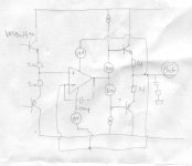
Note the 3.3 uH inductor in series with R2. As the frequency increases, the series combination reactance of R2 and the inductor will increase, rolling off the gain. I chose rather unusual choice of an inductor because it does not place exceptional demands on the opamp's drive current at high frequencies.
I also made provision for a small (47 pf) cap across R3 that could serve as a second pole of rolloff. However, I have not found the cap to be necessary.
Using a step response, I simulated the amp into various loads, including resistances as low as 1.5 ohms. I also simulated with 4 ohms || with 1 uf and 0.5 ohms. In no case did I see and ringing, and overshoot was limited to less than 1 cycle. It should be noted that the amp does utilize a zobel network where the output is inductively isolated by approx 2.2 uH.
Since the amps have only been working for a few days, I have not had time to exhaustively test with a wide range of loads. However, when driven with a square wave and presented with the 4 ohm || 1 uf and 0.5 ohm load, the output waveform showed no signs of ringing or other instability.
Edmond Stuart said:
Hi Jeff,
Now that I can have a look at your schematic (thx Klaus), I'm missing any form of frequency compensation. Are they somewhere hidden?
Also, could tell us something about the stability of your amp and the capability to drive capacitive loads.
Cheers, Edmond.
Edmond,
Note the 3.3 uH inductor in series with R2. As the frequency increases, the series combination reactance of R2 and the inductor will increase, rolling off the gain. I chose rather unusual choice of an inductor because it does not place exceptional demands on the opamp's drive current at high frequencies.
I also made provision for a small (47 pf) cap across R3 that could serve as a second pole of rolloff. However, I have not found the cap to be necessary.
Using a step response, I simulated the amp into various loads, including resistances as low as 1.5 ohms. I also simulated with 4 ohms || with 1 uf and 0.5 ohms. In no case did I see and ringing, and overshoot was limited to less than 1 cycle. It should be noted that the amp does utilize a zobel network where the output is inductively isolated by approx 2.2 uH.
Since the amps have only been working for a few days, I have not had time to exhaustively test with a wide range of loads. However, when driven with a square wave and presented with the 4 ohm || 1 uf and 0.5 ohm load, the output waveform showed no signs of ringing or other instability.
Hi, analog_guy,
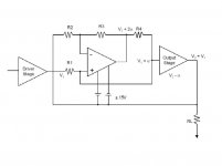
I'm thinking something like this (opamp corrector, but without resistor network). The supply is bootstrapped +/-15V towards output node. The compensation can be made by putting Ccomp between (-)input and output of the opamp.
Will this work?
Why do you make resistor network (several 100ohms) for your EC amp?
Attachments
Re: Re: Re: EC Amp Topology
Hi Jeff,
Ah, now I see. That resistor is also an inductor. Now it make sense. Together with 100Ohm, Fc of the error feedback is set at 4.8MHz, right?
BTW, why don't you use a more appropriate symbol for an inductor?
As for capacitive loads, I actually mean before the Zöbel network, i.e. directly tied to the output. Usually, an EC amp starts oscillating with a load of about 20nF. So I'm eager to know how your amp performs in this respect.
Cheers, Edmond.
analog_guy said:Edmond,
Note the 3.3 uH inductor in series with R2. As the frequency increases, the series combination reactance of R2 and the inductor will increase, rolling off the gain. I chose rather unusual choice of an inductor because it does not place exceptional demands on the opamp's drive current at high frequencies.
I also made provision for a small (47 pf) cap across R3 that could serve as a second pole of rolloff. However, I have not found the cap to be necessary.
Using a step response, I simulated the amp into various loads, including resistances as low as 1.5 ohms. I also simulated with 4 ohms || with 1 uf and 0.5 ohms. In no case did I see and ringing, and overshoot was limited to less than 1 cycle. It should be noted that the amp does utilize a zobel network where the output is inductively isolated by approx 2.2 uH.
Since the amps have only been working for a few days, I have not had time to exhaustively test with a wide range of loads. However, when driven with a square wave and presented with the 4 ohm || 1 uf and 0.5 ohm load, the output waveform showed no signs of ringing or other instability.
Hi Jeff,
Ah, now I see. That resistor is also an inductor. Now it make sense. Together with 100Ohm, Fc of the error feedback is set at 4.8MHz, right?
BTW, why don't you use a more appropriate symbol for an inductor?
As for capacitive loads, I actually mean before the Zöbel network, i.e. directly tied to the output. Usually, an EC amp starts oscillating with a load of about 20nF. So I'm eager to know how your amp performs in this respect.
Cheers, Edmond.
lumanauw said:Hi, analog_guy,
I'm thinking something like this (opamp corrector, but without resistor network). The supply is bootstrapped +/-15V towards output node. The compensation can be made by putting Ccomp between (-)input and output of the opamp.
Will this work?
Why do you make resistor network (several 100ohms) for your EC amp?
Hi lumanauw,
That's something different, an output stage corrected by means of ordinary NFB in stead of error FB. Nothing wrong with, quite the opposite.
Cheers, Edmond.
Hi, Edmond,
To get error FB, do we always have to use somekind of "voltage divider" network? I see this in Hawksford EC.
If this divider network is omitted, the term jumps to "ordinary NFB"?
To get error FB, do we always have to use somekind of "voltage divider" network? I see this in Hawksford EC.
If this divider network is omitted, the term jumps to "ordinary NFB"?
I have a dumb analogy. I'm sure it cannot be related engineeringly to audio power amp cct. A transistor has a limited capability. Even its magnification curve is not a straight line. So does a single man. What happens if in one company there's a single man has to do every job? Being a boss, being a worker, answering telephone, checking emails, sawing the wood, soldering, bending plates, wipe the floor, paying electricity, fix plumbing, changing light-bulbs, etc? If he can do all those jobs, all of them will be half done, none will be perfect.
Once I tought the so called "stage" in power amp can be counted with how many times the audio signal enters a base, and leave via emitor/collector. In this opinion, a common base does not fit for a "stage", so will a cascode, becase the signal does not come to its base (signal comes to emitor)
Then comes Nelson Pass. He has an opinion, a "stage" can be counted if a transistor contributes a gain (I assume this can be voltage or current gain). In this opinion, a current mirror is not a "stage".
Reading NP's tought, then I think further. Imagine a 3 stages power amp (input differential, VAS, output stage).
The input differential is like that person on the above example.
It has to : maintain 0dc offset, produce voltage gain (with VAS), maintaining gain factor (by feedback), taking care of the mess that the output stage made (Xover distortion), fix the mess at the output stage (cable+loudspeaker impedance), etc.
So I experimented to "distribute" those identified tasks to several transistors. I tought, a distributed job by several blocks will make the job more perfectly done. So far, it works.
This is why I'm interested in analog_guy's cct. That opamp takes care of the haviest burden, to watch for the output stage non-linearity. This way, the input differential has one less job (the heaviest) to do. It can concentrate to do better at the rest of the job, like providing cleaner voltage gain.
lumanauw said:Hi, Edmond,
To get error FB, do we always have to use somekind of "voltage divider" network? I see this in Hawksford EC.
If this divider network is omitted, the term jumps to "ordinary NFB"?
Hi lumanauw,
Yes indeed. The resistor network tries to give the op-amp an infinite gain (by means of positive FB) and this arrangement as a whole is used to minimize the distortion by means of negative FB (that's the NFB view on HEC as you know)
In your schematic just the open loop gain of the op-amp is used the reduce the distortion, instead of by the (almost) infinite gain of the EC circuit.
Notice that in real life we always need of kind of frequency compensation (which reduces the effective FB gain in both cases!), so in your schematic you have to put a resistor in the FB path from the output to the inverting input of the op-amp. Together with Ccomp, this RC combination determines the cut-off frequency of the FB loop.
Also notice that you will probably need a resistor in series with Ccomp in order to compensate for the roll off caused by the output stage proper.
Cheers, Edmond.
PS: Replace the op-amp by a couple of trannies and you will get my NFB-OPS. 😀
lumanauw said:Hi, Edmond,
To get error FB, do we always have to use somekind of "voltage divider" network? I see this in Hawksford EC.
If this divider network is omitted, the term jumps to "ordinary NFB"?
What I usually look for is a part of the topology that forms a positive feedback loop. This is generally consistent with the NFB view of EC, where, in some way, there is something that tries to make infinite loop gain via positive feedback. There are many non-EC topologies out there that are sometimes difficult to distinguish from EC.
Another way of looking at it is that the error is isolated and fed back to be summed with the input BEFORE that portion of the circuit where the error difference is determined. Then the act of correction does not act to diminish the error as measured (this is different than saying that it does not diminish the input-output error of the stage).
Cheers,
Bob
lumanauw said:Hi, analog_guy,
I'm thinking something like this (opamp corrector, but without resistor network). The supply is bootstrapped +/-15V towards output node. The compensation can be made by putting Ccomp between (-)input and output of the opamp.
Will this work?
Why do you make resistor network (several 100ohms) for your EC amp?
lumanauw,
My reason for using resistors is a consequence of how I defined the EC problem. Starting with the original analysis done by Bob Cordell, I wrote down the voltages at various nodes as shown in the attachment below. The output stage is assumed to introduce a error of -alpha; so the signal that must be presented to the left hand side of the output stage must be V1 + alpha. It turned out that one way of deriving that signal was to configure an opamp with a non-inverting gain of +2. My choice of 100 ohm resistors is based on the need to drive the output stage with a low impedance (R1 || R4 = 50 ohms) and the limit on the current drive capability of the opamp. There are undoubtedly other topologies that can achieve the same result, and some of them may simpler to implement.
Regarding the use of an opamp only without any resistors, I do not see any immediate reason why it would not work. However, it is important to examine stability. It should not be that difficult to simulate. I'll try to find time in the next few days to try it out with my SPICE deck.
Attachments
lumanauw said:I have a dumb analogy. I'm sure it cannot be related engineeringly to audio power amp cct. A transistor has a limited capability. Even its magnification curve is not a straight line. So does a single man. What happens if in one company there's a single man has to do every job? Being a boss, being a worker, answering telephone, checking emails, sawing the wood, soldering, bending plates, wipe the floor, paying electricity, fix plumbing, changing light-bulbs, etc? If he can do all those jobs, all of them will be half done, none will be perfect.
Once I tought the so called "stage" in power amp can be counted with how many times the audio signal enters a base, and leave via emitor/collector. In this opinion, a common base does not fit for a "stage", so will a cascode, becase the signal does not come to its base (signal comes to emitor)
Then comes Nelson Pass. He has an opinion, a "stage" can be counted if a transistor contributes a gain (I assume this can be voltage or current gain). In this opinion, a current mirror is not a "stage".
Reading NP's tought, then I think further. Imagine a 3 stages power amp (input differential, VAS, output stage).
The input differential is like that person on the above example.
It has to : maintain 0dc offset, produce voltage gain (with VAS), maintaining gain factor (by feedback), taking care of the mess that the output stage made (Xover distortion), fix the mess at the output stage (cable+loudspeaker impedance), etc.
So I experimented to "distribute" those identified tasks to several transistors. I tought, a distributed job by several blocks will make the job more perfectly done. So far, it works.
This is why I'm interested in analog_guy's cct. That opamp takes care of the haviest burden, to watch for the output stage non-linearity. This way, the input differential has one less job (the heaviest) to do. It can concentrate to do better at the rest of the job, like providing cleaner voltage gain.
lumanauw,
You bring up several good points that reflect some of the design tradeoffs which led me to implement EC. The first is that EC can effectively isolate the output stage from the input and voltage gain stages. There are good reasons for doing this. The first is that the feedback loop around the latter is output load independent. This approach avoids the loop gain/stability tradeoff that is inherent in any GFB design. The second is of a more practical nature: isolating the output stage allows for a modular design approach.
EC takes advantage of the fact that the output stage's gain is approximately unity and therefore the task of the EC amp may be limited to furnishing a small correction voltage to bring the stage's gain to almost unity. With lateral MOSFETS there is another advantage of EC, and that has to do with bandwidth of the EC stage. With a rolloff in the 5-10 MHz range, the loop gain of the EC stage is still large enough to supply ~35 dB of correction at 10 KHz. At lower frequencies that number goes up to ~55 dB. GFB would have difficulty achieving this amount of correction at high frequencies because the VAS stage is typically bandlimited in the 0.5 MHz range, and that stage therefore sets the overall NFB bandwidth and amount of loop gain available at high frequencies. Also, as I mentioned before, opening up the loop BW when using GFB can lead to instability problems.
Re: Re: Re: EC Amp Topology
Hi Jeff,
Instead of a series inductor, I have spiced your circuit with a parallel cap of 330pF across R1. I got the same performance and the same op-amp's drive current at 20kHz. With a square wave however, the drive current was about 50% higher.
Did you have tried this compensation scheme too?
Cheers, Edmond.
NB: I've used an ideal op-amp and a MOSFET-OPS.
analog_guy said:Edmond,
Note the 3.3 uH inductor in series with R2. As the frequency increases, the series combination reactance of R2 and the inductor will increase, rolling off the gain. I chose rather unusual choice of an inductor because it does not place exceptional demands on the opamp's drive current at high frequencies.
[snip]
Hi Jeff,
Instead of a series inductor, I have spiced your circuit with a parallel cap of 330pF across R1. I got the same performance and the same op-amp's drive current at 20kHz. With a square wave however, the drive current was about 50% higher.
Did you have tried this compensation scheme too?
Cheers, Edmond.
NB: I've used an ideal op-amp and a MOSFET-OPS.
Re: Re: Re: Re: EC Amp Topology
Edmond,
That sounds about right. I initially tried implementing a capacitive rolloff scheme.
Did you use an ideal opamp model or not? I found when I substituted an HSPICE macromodel for the EL2045 (available on the Intersil website) that I began to see stability problems at high amplitudes and edge rates. When simulating with a square wave take a close look at the edges to make sure there is no oscillation. It was the onset of stability (presumably caused by the current drive limitations of the EL2045) that prompted me to implement HF rolloff with the inductor.
Jeff
Edmond Stuart said:
Hi Jeff,
Instead of a series inductor, I have spiced your circuit with a parallel cap of 330pF across R1. I got the same performance and the same op-amp's drive current at 20kHz. With a square wave however, the drive current was about 50% higher.
Did you have tried this compensation scheme too?
Cheers, Edmond.
NB: I've used an ideal op-amp and a MOSFET-OPS.
Edmond,
That sounds about right. I initially tried implementing a capacitive rolloff scheme.
Did you use an ideal opamp model or not? I found when I substituted an HSPICE macromodel for the EL2045 (available on the Intersil website) that I began to see stability problems at high amplitudes and edge rates. When simulating with a square wave take a close look at the edges to make sure there is no oscillation. It was the onset of stability (presumably caused by the current drive limitations of the EL2045) that prompted me to implement HF rolloff with the inductor.
Jeff
Re: Re: Re: Re: Re: EC Amp Topology
Hi Jeff,
I've used an ideal op-amp, OL gain = 1e4 and infinite bandwidth.
Next week I'll try the macro model for the EL2045.
Cheers, Edmond.
analog_guy said:Edmond,
That sounds about right. I initially tried implementing a capacitive rolloff scheme.
Did you use an ideal opamp model or not? I found when I substituted an HSPICE macromodel for the EL2045 (available on the Intersil website) that I began to see stability problems at high amplitudes and edge rates. When simulating with a square wave take a close look at the edges to make sure there is no oscillation. It was the onset of stability (presumably caused by the current drive limitations of the EL2045) that prompted me to implement HF rolloff with the inductor.
Jeff
Hi Jeff,
I've used an ideal op-amp, OL gain = 1e4 and infinite bandwidth.
Next week I'll try the macro model for the EL2045.
Cheers, Edmond.
Edmond Stuart said:
Yes, except that (in a previous post) I meant by "HEC hoax" something different, i.e. HEC is equivalent to NFB.
Hi Edmond
Well, maybe EC is mathematically equivalent, but there is an interesting feature of error correction and not for feedback loop:
Error correction works as required around fairly linear and well defined stages, actually correction-efficiency is pretty proportional to initial linearity, feedback in cotrary can linearize circuits that are terribly non-linear and even time variant.
Consequently, EC becomes a correction beast as the circuit is more linear initially (read: has more local feedback). That's why I think EC works best as a turbo-boost to feedback.
All in all, any equivalence between EC and feedback is not very appealing to me, understanding EC as a different, alternative technique is damn appealing. If dr. Hawksford had given his article a name: "M.O.J. Hawksford: Well, just a bit different form of feedback, probably equivalent to tradinional one" would anyone ever get intersting in it ? 😉 😉
Best regards
Adam
darkfenriz said:
Hi Edmond
Well, maybe EC is mathematically equivalent, but there is an interesting feature of error correction and not for feedback loop:
Error correction works as required around fairly linear and well defined stages, actually correction-efficiency is pretty proportional to initial linearity, feedback in cotrary can linearize circuits that are terribly non-linear and even time variant.
Consequently, EC becomes a correction beast as the circuit is more linear initially (read: has more local feedback). That's why I think EC works best as a turbo-boost to feedback.
All in all, any equivalence between EC and feedback is not very appealing to me, understanding EC as a different, alternative technique is damn appealing. If dr. Hawksford had given his article a name: "M.O.J. Hawksford: Well, just a bit different form of feedback, probably equivalent to tradinional one" would anyone ever get intersting in it ? 😉 😉
Best regards
Adam
Hi Adam,
Obviously, I agree.
The fact that HEC can be analyzed as a form of NFB is very useful, and Edmond's demonstration that similar performance can be achieved with a conventional local output stage NFB arrangement is a very worthwhile contribution. That HEC can be analyzed as NFB, however, is certainly not something I would have called a Hoax.
I prefer the live-and-let-live approach to looking at HEC, where multiple valid views of the same thing are allowed to co-exist.
I'm glad that Hawksford described the technique the way he did, and that as a result it got the attention it deserved.
Cheers,
Bob
- Home
- Amplifiers
- Solid State
- Bob Cordell Interview: Error Correction