darkfenriz [B] [snip] That would be nesting said:Hi Adam,
Ah, now I get it! You are referring to your little gem (for example), the unbeatable 10 transistors amp with less than 10ppm distortion.
This wasn't obvious to me right from the beginning, as the previous discussion (with Bob et al) was narrowed to only output stages.
Cheers, Edmond.
Hi Adam
As most of us are not familiar with your little gem, any discussion about error correction in the way you have applied it, might be confusing.
So, why don't you show us the schematic as it has a couple of very intriguing features that broadens the scope of error correction.
Cheers, Edmond.
PS: You have mail.
Thank you Edmond!
I had no idea the contrast was so stark!
Is the subjective experience as starkly improved as the figures would suggest?
And does this not indicate that the principal culprit in a conventional PP AB amp is, in truth, the output stage? Is this simple, Vbe compression, or something less benign?
I'll be !@#$....... amazing!!!
Edmond, have you seen the Dartzeel output stage, a zero global nfb configuration?
Thoughts?
My apologies if this is off topic, but I'm trying to correlate these figures with the subjective results.... more resolution, better imaging, tighter bass, clearer vocals, less intermod, etc.
Cheers,
Hugh
Hi Hugh,
I too was surprised by the outcome, but don't forget that these figures are only based on one simulation. Maybe that the contrast is less pronounced with other topologies.
I think it is generally accepted now that the OPS is the principal culprit.
I haven't seen the Dartzeel output stage. What is it? A high-end distortion generator? Do you have a schematic?
Cheers, Edmond.
Hi Hugh,
I wouldn't say that the output stage is completely the reason for higher distortion. Loading down the Vas slightly with a stable load will even out the changes via the output stage. That might be counterintuitive, but it works.
The output stage has a lot asked of it. Just look at the change in currents through those parts. This will magnify any normal non-linearities the characterize a transistor. The EC techniques deliver a one - two punch to the entire distortion question. Linearizing the output stage and making the Vas load more consistent at the same time. That has got to be a good thing!
-Chris
Edmond Stuart said:
As most of us are not familiar with your little gem, any discussion about error correction in the way you have applied it, might be confusing.
So, why don't you show us the schematic as it has a couple of very intriguing features that broadens the scope of error correction.
I'd prefer to keep it somehow more personal for mow, anyone taking part in this thread interested in my design please send me an e-mail.
|
|
|
\/
AKSA said:Jan,
I second your comment; all praise to Bob, who has always remained fair, unbiased, and more than personable.
Bob,
Could I ask a simple question, from a guy who sells commercial amps of vastly simpler design than anything discussed here?
If we concentrate EC techniques on the output stage we are in fact preventing waveform compression on a unity gain stage. This is particularly significant on high level signals as they approach the rail, of course, and laudable.
However, if we assume that in a DEF output stage the Vbe increases to say 2V at max signal current and the drop across say a 0.22R emitter resistor at 6A is 1.32V, then the total compression is 3.32V maximum for an output of say 45V peak (assuming 50V rails). This implies an input signal off the VAS of around 48.32V, and thus gives an overall gain at peak current of 0.93. EC corrects this drop in gain to unity.
However, ordinarily, this slight loss of gain would be compensated by the global negative feedback loop, and in truth this compensation would be a walk in the park. Of far more significance would be variations in feedback factor caused by a high output impedance voltage amplifier as it struggles to negotiate the highly variable Zin of a DEF output stage. (I assume here a regular, conventional DEF, with which many may disagree, but for the purposes of the argument it's useful.)
Insofar as the EC output stage presents a far more uniform impedance to the VAS, I believe this is where you will obtain the majority of your benefits rather than the prevention of waveform compression at high signal levels.
Would you care to comment on this? Gospel, or garbage?
Cheers,
Hugh
Hi Hugh,
Thank you for your kind words.
I hope I'm not mis-understanding, but I assume by DEF you mean a double emitter follower output stage as aopposed to a Triple like the Locanthi T circuit.
My initial reaction is to say that I am not that familiar with applying EC to a DEF output stage. I usually prefer a triple in non-EC designs, and the buffering provided in my EC designs is probably equivalent to a Triple. I thus normally think in terms of the output transistors being driven by a pretty low impedance, especially at high frequencies where typical Miller compensation reduces the output impedance of the VAS and the double preceeding the output transistors provides a high amount of current gain.
For that reason I normally think of the EC as correcting the voltage transfer ratio of the output stage, especially in the crossover region.
However, I must say that I am also mystified by the results that Edmond has shown, assuming that I understand them properly. I do normally agree that the output stage is the biggest source of difficult-to-reduce distortion, but I do also normally think that the use of only a DEF is not enought to prevent avoidable distortion due to very finite and nonlinear beta of the output stage loading the VAS.
I would have been tempted to say that Edmond's exercise in adding in EC inadvertantly added much better buffering to the VAS, but it looks like he covered that base as well.
I hope I don't sound too confused here, and that I have not mis-interpreted your post.
Cheers,
Bob
Thank you Bob,
It's nice to know you too are amazed at Edmond's figures; this is a distortion reduction of almost 27 times, and it takes no account of the VAS, which I always believed to be the primary source of distortion.....
Edmond,
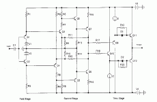
Thank you for your post. Here is the Dartzeel conceptual drawing. It is open loop, as I understand it, and very highly rated by Stereophile.
Cheers,
Hugh
It's nice to know you too are amazed at Edmond's figures; this is a distortion reduction of almost 27 times, and it takes no account of the VAS, which I always believed to be the primary source of distortion.....
Edmond,
Thank you for your post. Here is the Dartzeel conceptual drawing. It is open loop, as I understand it, and very highly rated by Stereophile.
Cheers,
Hugh
Attachments
Dartzeel
US Pat 6,882,225
distortion:
http://www.soundstagemagazine.com/measurements/dartzeel_nhb108_model_one/chart5.gif
US Pat 6,882,225
distortion:
http://www.soundstagemagazine.com/measurements/dartzeel_nhb108_model_one/chart5.gif
Hi,
All you want to know about the Dartzeel amplifier
patents !
http://jipihorn.free.fr/Brevets/WO03043185-FR.pdf
http://jipihorn.free.fr/Brevets/WO03043185-US.pdf
schematics and simulation
http://perso.wanadoo.fr/francis.audio2/Concours_Conception_Ampli_part2.doc
measurements
http://www.soundstagemagazine.com/measurements/dartzeel_nhb108_model_one/
manual
http://www.dartzeel.com/PDF_Files/AudioManuFR.pdf
googling "darTZeel"
Immodestly the ultimate audio power amplifier in the world, ...
www.dartzeel.com/
Reading the description of the power amp product, it seems his goal was to avoid any phase distortion at the expense of THD and IMD.forr said:
However, there is a notable false claim on that page when discussing the aural localization of sound sources from different vertical, but fixed lateral, positions.
First of all, the actual way the ears make that distinction is because the frequency response of the head and outer ear varies quite a bit depending on direction--this guy needs to read about HRTFs.
Second, listening to a stereo recording with speakers, it's simply impossible to produce the finer details of spatiality because of the limitations of recording and playback geometry. The only perfect reproduction of a sound field can be achieved with binaural recordings playing in in-ear-canal headphones--and even those only work perfectly when the pinnae of the dummy head used for the recording match sufficiently well that of the listener. To some extent DSP can emulate this for a given speaker setup, but only for a single small sweet spot. Simply put, spatial reproduction depends probably LEAST of all on the amplifier, in any given system. Of course, this fact doesn't sell amplifiers...
Edmond Stuart said:I haven't seen the Dartzeel output stage. What is it?
A ludicrously priced heap of poo.
abzug said:
Second, listening to a stereo recording with speakers, it's simply impossible to produce the finer details of spatiality because of the limitations of recording and playback geometry.
There is an even simpler explanation why the author's statements are not worth the electrons used to display on the monitor. I would be curious to find how the author could explain, based on the physics as we know it, how a 3D sound image (Quote: ...that acoustical images are fixed in space and have height and width and depth and localization.) could be reproduced using only two sources.
Actually, you are wrong, and your mistake of ignoring physiology is a common one--you forget that we only need to reproduce the signal at the eardrums, not an actual precise virtual 3D sphere around your head. You only have two ears, so with full information on the listening setup it's possible to reproduce full 3D imaging with two sound sources. You can do it with speakers instead of headphones for a fixed speaker and listener position; there's an awesome demonstration you can try of this by downloading the wave files here:syn08 said:I would be curious to find how the author could explain, based on the physics as we know it, how a 3D sound image (Quote: ...that acoustical images are fixed in space and have height and width and depth and localization.) could be reproduced using only two sources.
http://www.isvr.soton.ac.uk/FDAG/VAP/html/download.html
It will only work if you position the speakers and yourself as explained in the readme file. Once you position things correctly, the effect is great.
With advanced DSP and head-tracking in theory a setup where the listener can turn and move about is doable, though the software-based crosstalk cancellation can never be as good as when using headphones.
abzug said:
there's an awesome demonstration you can try of this by downloading the wave files here:
http://www.isvr.soton.ac.uk/FDAG/VAP/html/download.html
Admittently, I know close to nothing about physiology however I know a little about physics and still fail to understand how you could define/reconstruct a 3D image using only two sources.
I have tried the files using my computer speakers, following the instruction in the readme file, and I can't say I am convinced. The rest of the web site you mentioned is incomprehensible to me (including the other readme file) and the link to the PhD thesis is dead.
If you could quote some plain english resource on the topic, detailing the physical model used, it would be appreciated.
Edit: I got six hits in the AES library on Dr. Kahana's work. What he is doing makes a lot of sense, however I can't find any reference strictly on the current topic. Dealing with multichannel systems and modelling the acoustic field is a different kettle of fish.
AKSA said:Thank you Bob,
It's nice to know you too are amazed at Edmond's figures; this is a distortion reduction of almost 27 times, and it takes no account of the VAS, which I always believed to be the primary source of distortion.....
Edmond,
Thank you for your post. Here is the Dartzeel conceptual drawing. It is open loop, as I understand it, and very highly rated by Stereophile.
Cheers,
Hugh
Hi Hugh,
Thank you for the schematic of this musical instrument.
Very highly rated? Please read between the lines of that review. Also have a look at the distortion figures. Horrible.
But let's turn back to your 'gospel', as this thread is about error correction, not error creation.
Since you and Bob were amazed by the outcome of my simulation, I poked a little bit deeper into the blameless amp. At 20kHz, the output impedance (Zo) of the VAS is about 40 Ohm and the input impedance (Zi) of the output stage is about 200kOhm.
Now suppose that in case of an infinite Zo of the VAS, Zi varies to such a degree that it causes an additional open loop distortion of 5%. Then, in case of a real VAS, the effect of this variation is attenuated by a factor Zo/Zi = 5000, resulting in an extra distortion of 5%/5000 = 10ppm.
Let's further suppose that this distortion product consists only of the 3rd harmonic, ie 60kHz, and that at this frequency the NFB loop gain is 20dB, then above distortion component is further reduced to 1ppm.
Voilà, well in accordance with the difference between 136 and 137ppm. Are you still amazed?
Next, I spiced Bob's amp. Without EC it 'does' 87ppm at 20kHz and with an ideal buffer, inserted between the VAS and the OPS, it does 86ppm.
Cheers, Edmond.
Edmond Stuart said:
Hi Hugh,
Thank you for the schematic of this musical instrument.
Very highly rated? Please read between the lines of that review. Also have a look at the distortion figures. Horrible.
But let's turn back to your 'gospel', as this thread is about error correction, not error creation.
Since you and Bob were amazed by the outcome of my simulation, I poked a little bit deeper into the blameless amp. At 20kHz, the output impedance (Zo) of the VAS is about 40 Ohm and the input impedance (Zi) of the output stage is about 200kOhm.
Now suppose that in case of an infinite Zo of the VAS, Zi varies to such a degree that it causes an additional open loop distortion of 5%. Then, in case of a real VAS, the effect of this variation is attenuated by a factor Zo/Zi = 5000, resulting in an extra distortion of 5%/5000 = 10ppm.
Let's further suppose that this distortion product consists only of the 3rd harmonic, ie 60kHz, and that at this frequency the NFB loop gain is 20dB, then above distortion component is further reduced to 1ppm.
Voilà, well in accordance with the difference between 136 and 137ppm. Are you still amazed?
Next, I spiced Bob's amp. Without EC it 'does' 87ppm at 20kHz and with an ideal buffer, inserted between the VAS and the OPS, it does 86ppm.
Cheers, Edmond.
Hi Edmond,
This is very interesting. Could you post the schematics of the blameless amp that you simulted, both the straight DEF version and the one wherein you added the EC?
Thanks!
Bob
Hi,
Abzug is quite right on this. I have had my dealing with HRTF modelling (using the old but popular KEMAR data), and even very crude approximations can lead to quite astonishing results, rendering sources way outside the speaker baseline, laterally as well as vertically. Commercially, HRTF-based "3D-sound" (ok, "2.5D" might be more approbriate") is availably for example in "Q-Sound" recordings, and everybody can play with it themselves with e.g. the Prosonic Ambisone plug-in (VST interface), which can be tested in a demo version.
The big problem is that it really is very setup specific and personal factors also are quite important. The more precise the effect can be made to work with one specific setup and person, the more it might fail when the situation changes only slightly. That's why simpler models (like the ellipsoid in Kahana's approach) yield overall more stable results, at the cost of imperfection (which mainly shows up as unability to produce very sharp phantom images).
This can be partly overcome with a 2-Ch to 3-Ch matrixing, known in the literature as "optimum linear matrix, with maxtrix factor of 0.5" (by MilesTechnology, who also hold a patent on it), available in working units from a variety of manufacturers. With normal 2-Ch. reproduction the sweetspot is narrow, but quite long. With the rematrixing it gets wider but shorter and is more benign to head movement (especially head turns). The current HRTF tricks are based on and rely on the normal stereo triangle, they need to be adapted to work with that revectoring. This method allows closer approximation of a sort of wave field synthesis around the listeners head, which in essence is all that counts. More precisely, the steady state part of it is quite sufficient for a good illusion. The initial direction of incident wavefronts cannot not be exactly realistic, which is obvious. But our minds don't mind, they can be fooled quite easily
Sorry to have sidetracked this thread a little,
Klaus
abzug said:Actually, you are wrong, and your mistake of ignoring physiology is a common one--you forget that we only need to reproduce the signal at the eardrums, not an actual precise virtual 3D sphere around your head. You only have two ears, so with full information on the listening setup it's possible to reproduce full 3D imaging with two sound sources.
Abzug is quite right on this. I have had my dealing with HRTF modelling (using the old but popular KEMAR data), and even very crude approximations can lead to quite astonishing results, rendering sources way outside the speaker baseline, laterally as well as vertically. Commercially, HRTF-based "3D-sound" (ok, "2.5D" might be more approbriate") is availably for example in "Q-Sound" recordings, and everybody can play with it themselves with e.g. the Prosonic Ambisone plug-in (VST interface), which can be tested in a demo version.
The big problem is that it really is very setup specific and personal factors also are quite important. The more precise the effect can be made to work with one specific setup and person, the more it might fail when the situation changes only slightly. That's why simpler models (like the ellipsoid in Kahana's approach) yield overall more stable results, at the cost of imperfection (which mainly shows up as unability to produce very sharp phantom images).
This can be partly overcome with a 2-Ch to 3-Ch matrixing, known in the literature as "optimum linear matrix, with maxtrix factor of 0.5" (by MilesTechnology, who also hold a patent on it), available in working units from a variety of manufacturers. With normal 2-Ch. reproduction the sweetspot is narrow, but quite long. With the rematrixing it gets wider but shorter and is more benign to head movement (especially head turns). The current HRTF tricks are based on and rely on the normal stereo triangle, they need to be adapted to work with that revectoring. This method allows closer approximation of a sort of wave field synthesis around the listeners head, which in essence is all that counts. More precisely, the steady state part of it is quite sufficient for a good illusion. The initial direction of incident wavefronts cannot not be exactly realistic, which is obvious. But our minds don't mind, they can be fooled quite easily
Sorry to have sidetracked this thread a little,
Klaus
By properly encoding the information in a perceptually appropriate way. In the case of audio, it's encoded with knowledge of how the frequency response of the ear varies with direction.syn08 said:Admittently, I know close to nothing about physiology however I know a little about physics and still fail to understand how you could define/reconstruct a 3D image using only two sources.
The ear's frequency response when measured for a sound source with a specific location, if the resolution of the measurement is sufficient, what is noticeable is a series of dense, narrow troughs in the graph, and a shift in location of the sound source with respect to the ear will cause a significant change in these detailed areas of the frequency response. Together with relative frequency and phase response between the ears (timing as well--the ear performs both frequency- and time-based analysis), two ears give 3D perception.
Of course, resolving a 3D sound field with just two stationary sensors is an ill-defined problem because one can come up with an infinite variety of inputs that produce the same sensory outcome--that's why they can be fooled by a speaker setup. Another good example is that of 3D vision--with your two eyes you have depth perception, because when the eyes' foveas focus on a point, the brain triangulates depth from the angle between the optical axes (actually, 3D vision also uses information from accommodation (focusing for different distances) as well as shading and geometrical cues such relative sizes and motion parallax). But, of course, 3D from stereo is also an ill-defined problem, since it depends on the ability to figure out which point from the image in one eye corresponds to which point in the image from the other eye. Our brains do it very well in a typical Earth environment and make certain likelihood assumptions, but it's quite easy to come up with visual illusions that produce perception of a 3D scene that doesn't correspond with reality. Holograms, VR glasses, and more recently, 3D monitors that manage this without any glasses, are examples. Indeed, this goes for most perception problems, where probabilistic assumptions about the world are used by the brain, as well as researchers in machine perception, to produce a solution from restricted sensory data. My other favorite example from vision research is that of shape from shading, where the brain (or algorithm) assume uniform directional illumination to solve that ill-defined problem.
The point is that when one is talking about sensory issues, well defined problems with general solutions do not exist--but it's not really necessary anyway, since the world is not structured arbitrarily and the additional information that these assumptions provide is what allows such ill-defined problems to be solved.
Also, what KSTR said
I should mention also that HRTF determination is very expensive and time-consuming since you need an anechoic chamber and suspension of the listener in the center of a sphere covered with speakers, then testing the ear responses to sound from a large number of directions--the more, the better. That makes it quite impractical to have a very large library of HRTFs, so there's a body of research attempting to estimate HRTFs from simplified measurements.
But the most interesting approach is that of laser scanning the head, which takes a few minutes, and then running a simulation of sound propagation on a powerful computer. Last time I checked, one needs about 4 GB of RAM with the state of the art algorithm and a few days on a modern CPU. A laser scanner can be had for a few hundred dollars. It seems to me pretty soon it would be possible for everyone to have their HRTF found, and with advances in DSP, the possibilities for true high quality sound imaging will open up 😀
abzug said:
By properly encoding the information in a perceptually appropriate way. In the case of audio, it's encoded with knowledge of how the frequency response of the ear varies with direction.
The ear's frequency response when measured for a sound source with a specific location, if the resolution of the measurement is sufficient, what is noticeable is a series of dense, narrow troughs in the graph, and a shift in location of the sound source with respect to the ear will cause a significant change in these detailed areas of the frequency response. Together with relative frequency and phase response between the ears (timing as well--the ear performs both frequency- and time-based analysis), two ears give 3D perception.
Of course, resolving a 3D sound field with just two stationary sensors is an ill-defined problem because one can come up with an infinite variety of inputs that produce the same sensory outcome--that's why they can be fooled by a speaker setup. Another good example is that of 3D vision--with your two eyes you have depth perception, because when the eyes' foveas focus on a point, the brain triangulates depth from the angle between the optical axes (actually, 3D vision also uses information from accommodation (focusing for different distances) as well as shading and geometrical cues such relative sizes and motion parallax). But, of course, 3D from stereo is also an ill-defined problem, since it depends on the ability to figure out which point from the image in one eye corresponds to which point in the image from the other eye. Our brains do it very well in a typical Earth environment and make certain likelihood assumptions, but it's quite easy to come up with visual illusions that produce perception of a 3D scene that doesn't correspond with reality. Holograms, VR glasses, and more recently, 3D monitors that manage this without any glasses, are examples. Indeed, this goes for most perception problems, where probabilistic assumptions about the world are used by the brain, as well as researchers in machine perception, to produce a solution from restricted sensory data. My other favorite example from vision research is that of shape from shading, where the brain (or algorithm) assume uniform directional illumination to solve that ill-defined problem.
The point is that when one is talking about sensory issues, well defined problems with general solutions do not exist--but it's not really necessary anyway, since the world is not structured arbitrarily and the additional information that these assumptions provide is what allows such ill-defined problems to be solved.
Also, what KSTR said
I should mention also that HRTF determination is very expensive and time-consuming since you need an anechoic chamber and suspension of the listener in the center of a sphere covered with speakers, then testing the ear responses to sound from a large number of directions--the more, the better. That makes it quite impractical to have a very large library of HRTFs, so there's a body of research attempting to estimate HRTFs from simplified measurements.
But the most interesting approach is that of laser scanning the head, which takes a few minutes, and then running a simulation of sound propagation on a powerful computer. Last time I checked, one needs about 4 GB of RAM with the state of the art algorithm and a few days on a modern CPU. A laser scanner can be had for a few hundred dollars. It seems to me pretty soon it would be possible for everyone to have their HRTF found, and with advances in DSP, the possibilities for true high quality sound imaging will open up 😀
Thanks, now that you put this as an encoding problem, it starts making sense.
But then what has a power amp (and in general negative feedback) to do with the process of encoding the audio information? Would it be possible to define a set of objective criteria to optimize the audio equipment in reproducing the encoded audio information?
- Home
- Amplifiers
- Solid State
- Bob Cordell Interview: Error Correction