Re: Re: Re: hec != hoax ?
I was thinking about those 5 little VDC symbols sitting like thorns in my eyes 🙂)
Edmond Stuart said:
I really hate bias circuits that cripple the VAS 😀
I was thinking about those 5 little VDC symbols sitting like thorns in my eyes 🙂)
lumanauw said:Hi, Edmond,
Discussing about VAS drive, what is your opinion about this kind of VAS drive? This is from SKA topology. It boost the gain of the VAS drive, (making it high impedance) by using bootstrap (R2+R3+C2). Then feeded to emitor follower Q5. From here, it drives the VAS stage (Q7-Q8, but here Q7-Q8 are already power devices).
Hi lumanauw,
What else could I say about this circuit, as most ins and outs you have already figured out by yourself.
To be honest, I don't like this circuit at all, because the bias of the output stage is not well controlled, for example.
Cheers, Edmond.
Attachments
In Greg's actual design, the input stage current sources are a function of heat sink temperature to compensate the output stage bias. I had some email conversations with him about this a couple of years ago. He was trying to get me to tweak the level 3 SPICE models of his output devices so the simulated and measured tempco agreed. It looked too time consuming, so I gave up on it.
Hi,
@Edmond:
Thanks for elaborating on the VAS details... I get a clearer picture now (still it's not intuitive to me... I need to sim it to really get it, it seems). Also, that 40ppb THD20 @300mA is really stunning, though I assume this figure is for the complete amp, not the OS in isolation.
@all, FWIW: Here I played a little with that autobias class A OS, and as it deals a little with error correction / feedback in two regards (#1: error cross-feed, #2: separating voltage and current terms in the feedback loops) you might want to take a look there (comments welcome). As of now, I abandoned the output stage concept I posted here a while ago, since this autobias thing does the same performance with lower parts count and simpler topology, all cheap discrete stuff.
- Klaus
Re: Re: Re: Re: hec != hoax ?
Hi Ovidiu,
Thorns are gone. 🙂
Cheers, Edmond.
NB: This is not a complete amp: no protection, no Zobel network, no servo etc.
syn08 said:
I was thinking about those 5 little VDC symbols sitting like thorns in my eyes 🙂)
Hi Ovidiu,
Thorns are gone. 🙂
Cheers, Edmond.
NB: This is not a complete amp: no protection, no Zobel network, no servo etc.
Attachments
Re: Re: Re: Re: Re: hec != hoax ?
They are 🙂
Now, how would you compare this design complexity with respect to the PGP amp?
But after considering each amp simulated performance?
Edmond Stuart said:
Thorns are gone. 🙂
NB: This is not a complete amp: no protection, no Zobel network, no servo etc.
They are 🙂
Now, how would you compare this design complexity with respect to the PGP amp?
But after considering each amp simulated performance?
Re: Re: Re: Re: Re: Re: hec != hoax ?
Hi Ovidiu,
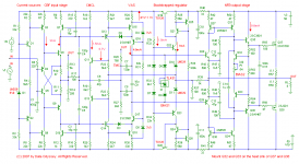
Of course the front end is less complex, as it lacks a NDFL stage. Nevertheless, due to TMC, the distortion is about at the same level.
OTOH, the offset voltage is quite large (0.5V), so a servo needed, which adds to complexity (an op-amp, +/- 15 PSU, etc.).
Notice that this is not just a TMC amp, rather a double TMC amp (DTMC). Not only the take off point is 'TMCed' (see: R26-27 and C7-8), but also the feedback input for the Miller compensation is 'TMCed' (see: R17 and C4-5). As a result, at AF the Miller cap (C6) is effectively connected from the output right to the inverting input, while at HF the Miller cap is effectively connected between VAS input and VAS output. This arrangement ensures an extreme low distortion of the front end and a very modest drive requirement of the input stage (biased at a mere 1mA).
BTW, DTMC is only compatible with a CFB input stage, thus no LTP, let alone configurations with an additional gain stage between the IPS and VAS.
Cheers, Edmond.
syn08 said:They are 🙂
Now, how would you compare this design complexity with respect to the PGP amp?
But after considering each amp simulated performance?
Hi Ovidiu,
Of course the front end is less complex, as it lacks a NDFL stage. Nevertheless, due to TMC, the distortion is about at the same level.
OTOH, the offset voltage is quite large (0.5V), so a servo needed, which adds to complexity (an op-amp, +/- 15 PSU, etc.).
Notice that this is not just a TMC amp, rather a double TMC amp (DTMC). Not only the take off point is 'TMCed' (see: R26-27 and C7-8), but also the feedback input for the Miller compensation is 'TMCed' (see: R17 and C4-5). As a result, at AF the Miller cap (C6) is effectively connected from the output right to the inverting input, while at HF the Miller cap is effectively connected between VAS input and VAS output. This arrangement ensures an extreme low distortion of the front end and a very modest drive requirement of the input stage (biased at a mere 1mA).
BTW, DTMC is only compatible with a CFB input stage, thus no LTP, let alone configurations with an additional gain stage between the IPS and VAS.
Cheers, Edmond.
Re: Re: Re: Re: Re: Re: Re: hec != hoax ?
Hi Edmond,
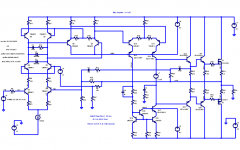
Although I don't call it "DTMC", the approach of taking the TMC path from the output of the amplifier back to the input is the way I have applied TMC to my input/VAS architecture. That is a fairly obvious extension of my favorite type of feedback compensation to TMC. Indeed, TMC inclusive of the input stage is quite compatible with an LTP input stage as shown in the schematic below.
That simulation yielded 0.001% THD-20 out to 200 kHz at 100 watts into 8 ohms with a simple and straightforward version of my amplifier that did not use EC.
The TMC path includes C5, C2 and R36.
Note also that the input cascode is bootstrapped with a replica of the input signal derived from the output signal via R3 and R27. I have found that doing so reduces a significant contributor to distortion that was in my original MOSFET amplifier design.
No Early effect mitigation is used in the VAS of this simple design.
Cheers,
Bob
Edmond Stuart said:
Hi Ovidiu,
Of course the front end is less complex, as it lacks a NDFL stage. Nevertheless, due to TMC, the distortion is about at the same level.
OTOH, the offset voltage is quite large (0.5V), so a servo needed, which adds to complexity (an op-amp, +/- 15 PSU, etc.).
Notice that this is not just a TMC amp, rather a double TMC amp (DTMC). Not only the take off point is 'TMCed' (see: R26-27 and C7-8), but also the feedback input for the Miller compensation is 'TMCed' (see: R17 and C4-5). As a result, at AF the Miller cap (C6) is effectively connected from the output right to the inverting input, while at HF the Miller cap is effectively connected between VAS input and VAS output. This arrangement ensures an extreme low distortion of the front end and a very modest drive requirement of the input stage (biased at a mere 1mA).
BTW, DTMC is only compatible with a CFB input stage, thus no LTP, let alone configurations with an additional gain stage between the IPS and VAS.
Cheers, Edmond.
Hi Edmond,
Although I don't call it "DTMC", the approach of taking the TMC path from the output of the amplifier back to the input is the way I have applied TMC to my input/VAS architecture. That is a fairly obvious extension of my favorite type of feedback compensation to TMC. Indeed, TMC inclusive of the input stage is quite compatible with an LTP input stage as shown in the schematic below.
That simulation yielded 0.001% THD-20 out to 200 kHz at 100 watts into 8 ohms with a simple and straightforward version of my amplifier that did not use EC.
The TMC path includes C5, C2 and R36.
Note also that the input cascode is bootstrapped with a replica of the input signal derived from the output signal via R3 and R27. I have found that doing so reduces a significant contributor to distortion that was in my original MOSFET amplifier design.
No Early effect mitigation is used in the VAS of this simple design.
Cheers,
Bob
Attachments
Re: Re: Re: Re: Re: Re: Re: hec != hoax ?
It would be interesting to describe the pros and cons for each approach (NDFL vs. TMC). If the performance (not only THD20, but also PSRR, SR, IMD, DIM, etc...) is the same, then why/how would one chose between NDFL and TMC?
You know I am a little skeptic regarding TMC (in particular about delivering under 1ppm THD20 with a reasonable phase margin). I have to build and measure such an amp to find if it really delivers to te expectations and better understand what's the price of this approach and how it would compare to NDFL.
As a rule, I think it would be always a good idea to show both sides of a certain new design approach. As you know, there is no free lunch... Maybe defining a consistent set of parameters against each design should be evaluated, both from a simulation and measurements perspective, would help?
BTW, another issue that must be addressed to make such designs more appealing is to make the simulation results reproductible. Unfortunately, it seems that PSpice (at least the Cadence/OrCad version that I am using) is unable to always reproduce your numbers, even for simpler designs and even if the device models are identical. I think it would be a good idea to define a set of simulation benchmarks, to provide consistency across platforms. I think this is important in particular for "sensitive" topics like THD, IMD, etc... and I don't think it's realistic to expect that everybody should use and trust Micro-Cap.
I know, unfortunately there's nothing sexy in such work, but I don't think there's other way to raise the level of confidence in a certain design. Of course, I am assuming you find confidence and results consistency important.
Edmond Stuart said:
Hi Ovidiu,
Of course the front end is less complex, as it lacks a NDFL stage. Nevertheless, due to TMC, the distortion is about at the same level.
OTOH, the offset voltage is quite large (0.5V), so a servo needed, which adds to complexity (an op-amp, +/- 15 PSU, etc.).
Notice that this is not just a TMC amp, rather a double TMC amp (DTMC). Not only the take off point is 'TMCed' (see: R26-27 and C7-8), but also the feedback input for the Miller compensation is 'TMCed' (see: R17 and C4-5). As a result, at AF the Miller cap (C6) is effectively connected from the output right to the inverting input, while at HF the Miller cap is effectively connected between VAS input and VAS output. This arrangement ensures an extreme low distortion of the front end and a very modest drive requirement of the input stage (biased at a mere 1mA).
BTW, DTMC is only compatible with a CFB input stage, thus no LTP, let alone configurations with an additional gain stage between the IPS and VAS.
Cheers, Edmond.
It would be interesting to describe the pros and cons for each approach (NDFL vs. TMC). If the performance (not only THD20, but also PSRR, SR, IMD, DIM, etc...) is the same, then why/how would one chose between NDFL and TMC?
You know I am a little skeptic regarding TMC (in particular about delivering under 1ppm THD20 with a reasonable phase margin). I have to build and measure such an amp to find if it really delivers to te expectations and better understand what's the price of this approach and how it would compare to NDFL.
As a rule, I think it would be always a good idea to show both sides of a certain new design approach. As you know, there is no free lunch... Maybe defining a consistent set of parameters against each design should be evaluated, both from a simulation and measurements perspective, would help?
BTW, another issue that must be addressed to make such designs more appealing is to make the simulation results reproductible. Unfortunately, it seems that PSpice (at least the Cadence/OrCad version that I am using) is unable to always reproduce your numbers, even for simpler designs and even if the device models are identical. I think it would be a good idea to define a set of simulation benchmarks, to provide consistency across platforms. I think this is important in particular for "sensitive" topics like THD, IMD, etc... and I don't think it's realistic to expect that everybody should use and trust Micro-Cap.
I know, unfortunately there's nothing sexy in such work, but I don't think there's other way to raise the level of confidence in a certain design. Of course, I am assuming you find confidence and results consistency important.
Re: Re: Re: Re: Re: Re: Re: Re: hec != hoax ?
Hi Bob,
Perhaps you should have a closer look at my latest schematic. I insist that it is DTMC, not just TMC, because:
"also the feedback input for the Miller compensation is 'TMCed' (see: R17 and C4-5). As a result, at AF the Miller cap (C6) is effectively connected from the output right to the inverting input, while at HF the Miller cap is effectively connected between VAS input and VAS output."
Before making any comment on your schematic, please increase the font size, as the component values are hard to identify.
Cheers, Edmond.
Bob Cordell said:Hi Edmond,
Although I don't call it "DTMC", the approach of taking the TMC path from the output of the amplifier back to the input is the way I have applied TMC to my input/VAS architecture. That is a fairly obvious extension of my favorite type of feedback compensation to TMC. Indeed, TMC inclusive of the input stage is quite compatible with an LTP input stage as shown in the schematic below.
That simulation yielded 0.001% THD-20 out to 200 kHz at 100 watts into 8 ohms with a simple and straightforward version of my amplifier that did not use EC.
The TMC path includes C5, C2 and R36.
Note also that the input cascode is bootstrapped with a replica of the input signal derived from the output signal via R3 and R27. I have found that doing so reduces a significant contributor to distortion that was in my original MOSFET amplifier design.
No Early effect mitigation is used in the VAS of this simple design.
Cheers,
Bob
Hi Bob,
Perhaps you should have a closer look at my latest schematic. I insist that it is DTMC, not just TMC, because:
"also the feedback input for the Miller compensation is 'TMCed' (see: R17 and C4-5). As a result, at AF the Miller cap (C6) is effectively connected from the output right to the inverting input, while at HF the Miller cap is effectively connected between VAS input and VAS output."
Before making any comment on your schematic, please increase the font size, as the component values are hard to identify.
Cheers, Edmond.
Re: Re: Re: Re: Re: Re: Re: Re: hec != hoax ?
Hi Ovidiu,
These are all very, very good questions, and the approach to evaluation you have suggested, would more than likely move the ball forward.
In some cases, two different approaches might yield equal performance on paper, but differences in implementation detail might make one ultimately capable of higher performance, for example.
I have been very impressed by the forward progress made among us in the use of SPICE for distortion analysis and the level of confidence in those results. I'm sure they are not perfect, however, and being able to exchange benchmarks on the same simulators, or, better yet, be able to get virtually the same results on different simulators would be great.
At the very least, I think that we have discovered that SPICE distortion simulations are fairly reliable for comparison purposes where we tweak a circuit and see how the change affects SPICE-reported distortion. This is extremely valuable, even if the absolute value of distortion reported is optimistic or pessimistic by some factor (I believe it can go either way).
I must admit that I've never used Micro-Cap, but it must be extraordinarily good based on what I've heard some people say about it in comparison to LTSPICE. Quite frankly, I have been extremely happy with LTSPICE, including its speed and user interface. That it is free is a huge reason to try to exchange benchmarks with it as the default simulator, I think.
Cheers,
Bob
syn08 said:
It would be interesting to describe the pros and cons for each approach (NDFL vs. TMC). If the performance (not only THD20, but also PSRR, SR, IMD, DIM, etc...) is the same, then why/how would one chose between NDFL and TMC?
You know I am a little skeptic regarding TMC (in particular about delivering under 1ppm THD20 with a reasonable phase margin). I have to build and measure such an amp to find if it really delivers to te expectations and better understand what's the price of this approach and how it would compare to NDFL.
As a rule, I think it would be always a good idea to show both sides of a certain new design approach. As you know, there is no free lunch... Maybe defining a consistent set of parameters against each design should be evaluated, both from a simulation and measurements perspective, would help?
BTW, another issue that must be addressed to make such designs more appealing is to make the simulation results reproductible. Unfortunately, it seems that PSpice (at least the Cadence/OrCad version that I am using) is unable to always reproduce your numbers, even for simpler designs and even if the device models are identical. I think it would be a good idea to define a set of simulation benchmarks, to provide consistency across platforms. I think this is important in particular for "sensitive" topics like THD, IMD, etc... and I don't think it's realistic to expect that everybody should use and trust Micro-Cap.
I know, unfortunately there's nothing sexy in such work, but I don't think there's other way to raise the level of confidence in a certain design. Of course, I am assuming you find confidence and results consistency important.
Hi Ovidiu,
These are all very, very good questions, and the approach to evaluation you have suggested, would more than likely move the ball forward.
In some cases, two different approaches might yield equal performance on paper, but differences in implementation detail might make one ultimately capable of higher performance, for example.
I have been very impressed by the forward progress made among us in the use of SPICE for distortion analysis and the level of confidence in those results. I'm sure they are not perfect, however, and being able to exchange benchmarks on the same simulators, or, better yet, be able to get virtually the same results on different simulators would be great.
At the very least, I think that we have discovered that SPICE distortion simulations are fairly reliable for comparison purposes where we tweak a circuit and see how the change affects SPICE-reported distortion. This is extremely valuable, even if the absolute value of distortion reported is optimistic or pessimistic by some factor (I believe it can go either way).
I must admit that I've never used Micro-Cap, but it must be extraordinarily good based on what I've heard some people say about it in comparison to LTSPICE. Quite frankly, I have been extremely happy with LTSPICE, including its speed and user interface. That it is free is a huge reason to try to exchange benchmarks with it as the default simulator, I think.
Cheers,
Bob
Re: Re: Re: Re: Re: Re: Re: Re: Re: hec != hoax ?
Hi Edmond,
Sorry, I guess I mistook your definition of DTMC. I guess by some definition C4-5 create a TMC loop within a TMC loop. In that case, it is different than what I thought you meant by DTMC. Mine doesn't have/need that, so I can't be sure what that feature of yours brings to the table. Maybe strictly dependent on the details of the implementation.
Cheers,
Bob
Edmond Stuart said:
Hi Bob,
Perhaps you should have a closer look at my latest schematic. I insist that it is DTMC, not just TMC, because:
"also the feedback input for the Miller compensation is 'TMCed' (see: R17 and C4-5). As a result, at AF the Miller cap (C6) is effectively connected from the output right to the inverting input, while at HF the Miller cap is effectively connected between VAS input and VAS output."
Before making any comment on your schematic, please increase the font size, as the component values are hard to identify.
Cheers, Edmond.
Hi Edmond,
Sorry, I guess I mistook your definition of DTMC. I guess by some definition C4-5 create a TMC loop within a TMC loop. In that case, it is different than what I thought you meant by DTMC. Mine doesn't have/need that, so I can't be sure what that feature of yours brings to the table. Maybe strictly dependent on the details of the implementation.
Cheers,
Bob
Re: Re: Re: Re: Re: hec != hoax ?
Hi Bod,
Indeed, it's a TMC loop within a TMC loop. 😀
What do you mean with: "Mine doesn't ...need that"? If you are satisfied with 10ppm, okay, but weren't we talking about sub-ppm amps?
BTW, where is the readable version of your schematic?
Cheers, Edmond.
Bob Cordell said:Hi Edmond,
Sorry, I guess I mistook your definition of DTMC. I guess by some definition C4-5 create a TMC loop within a TMC loop. In that case, it is different than what I thought you meant by DTMC. Mine doesn't have/need that, so I can't be sure what that feature of yours brings to the table. Maybe strictly dependent on the details of the implementation.
Cheers,
Bob
Hi Bod,
Indeed, it's a TMC loop within a TMC loop. 😀
What do you mean with: "Mine doesn't ...need that"? If you are satisfied with 10ppm, okay, but weren't we talking about sub-ppm amps?
BTW, where is the readable version of your schematic?
Cheers, Edmond.
Re: Re: Re: Re: Re: hec != hoax ?
Hi Ovidiu,
Provided that the output stage is the main source of distortion and provided that the Ft (or Fc) is equal, all these techniques TMC, HEC, NFB and NDFL reduce the distortion to the same amount (because of the 6dB/octave roll off).
TMC is the most simple one, but requires a good VAS.
HEC requires precision resistors and steals precious volts from the VAS.
NFB, is more efficient in this respect, but needs a separate bias generator.
NDFL is quite complex and need a 'nested clamp' to recover gracefully from overload.
From above, one may conclude that HEC, the ordinary NFB variant and NDFL is a kludge, because the same job can be done with TMC (only one extra C and R!). Ironically, this is not the case as both techniques can be combined with TMC, giving an even lower distortion (see my latest design).
As for simulators, you didn't tell me about troubles with the NFB-OPS, but as soon as circumstances allow me, I'll try Orcad.
BTW, how good is Orcad? Do you remember the trouble we had with the 'obstinate clamp'? It was that f*cking Orcad that cost us blood, sweat and tears.
Cheers, Edmond.
syn08 said:It would be interesting to describe the pros and cons for each approach (NDFL vs. TMC). If the performance (not only THD20, but also PSRR, SR, IMD, DIM, etc...) is the same, then why/how would one chose between NDFL and TMC?
You know I am a little skeptic regarding TMC (in particular about delivering under 1ppm THD20 with a reasonable phase margin). I have to build and measure such an amp to find if it really delivers to te expectations and better understand what's the price of this approach and how it would compare to NDFL.
As a rule, I think it would be always a good idea to show both sides of a certain new design approach. As you know, there is no free lunch... Maybe defining a consistent set of parameters against each design should be evaluated, both from a simulation and measurements perspective, would help?
BTW, another issue that must be addressed to make such designs more appealing is to make the simulation results reproductible. Unfortunately, it seems that PSpice (at least the Cadence/OrCad version that I am using) is unable to always reproduce your numbers, even for simpler designs and even if the device models are identical. I think it would be a good idea to define a set of simulation benchmarks, to provide consistency across platforms. I think this is important in particular for "sensitive" topics like THD, IMD, etc... and I don't think it's realistic to expect that everybody should use and trust Micro-Cap.
I know, unfortunately there's nothing sexy in such work, but I don't think there's other way to raise the level of confidence in a certain design. Of course, I am assuming you find confidence and results consistency important.
Hi Ovidiu,
Provided that the output stage is the main source of distortion and provided that the Ft (or Fc) is equal, all these techniques TMC, HEC, NFB and NDFL reduce the distortion to the same amount (because of the 6dB/octave roll off).
TMC is the most simple one, but requires a good VAS.
HEC requires precision resistors and steals precious volts from the VAS.
NFB, is more efficient in this respect, but needs a separate bias generator.
NDFL is quite complex and need a 'nested clamp' to recover gracefully from overload.
From above, one may conclude that HEC, the ordinary NFB variant and NDFL is a kludge, because the same job can be done with TMC (only one extra C and R!). Ironically, this is not the case as both techniques can be combined with TMC, giving an even lower distortion (see my latest design).
As for simulators, you didn't tell me about troubles with the NFB-OPS, but as soon as circumstances allow me, I'll try Orcad.
BTW, how good is Orcad? Do you remember the trouble we had with the 'obstinate clamp'? It was that f*cking Orcad that cost us blood, sweat and tears.
Cheers, Edmond.
Edmond Stuart said:
Hi Bod,
Indeed, it's a TMC loop within a TMC loop. 😀
What do you mean with: "Mine doesn't ...need that"? If you are satisfied with 10ppm, okay, but weren't we talking about sub-ppm amps?
BTW, where is the readable version of your schematic?
Cheers, Edmond.
Hi Edmond,
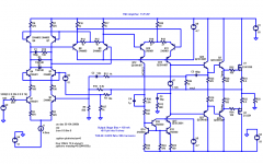
Mine doesn't need that extra loop for stability. It is not at all clear to me that your nested TMC approach is needed to get below 1 ppm when an otherwise very linear input/VAS stage is used.
As I thought I made clear, this was just a simple amplifier using TMC with my input/VAS topology. I was not shooting for 1 ppm. I was actually trying to compare the effect of TMC with the effect of EC within the basic topology of my original 25-year-old amplifier. As I stated, there is no Early effect mitigation in the VAS, and there is neither EC nor local feedback in the output stage.
The schematic with larger fonts is attached.
Cheers,
Bob
Attachments
TMC vs HEC
Hi Bob,
Given the weakness and shortcomings of simulations, I always choose the best solution, just to be on the safe side and in particular when it cost almost nothing. DTMC in my design increased the phase margin of the Miller loop to 95 degrees and the gain margin to 29dB. These are very nice figurers, you can't deny it, do you?
Okay, you wasn't shooting for 1 ppm, just exploring TMC. I'm glad you got essentially the same results as I got. In the mean time I simmed your circuit and I got THD20 = 15ppm in stead of 10ppm, never mind.
BUT more importantly, when I decreased the TMC resistor R36 from 1K to 330 Ohm, that means that Ft of the TMC network equals the Fc of your HEC NFB loop, the distortion is just the same, 6ppm
Cheers, Edmond.
Bob Cordell said:Hi Edmond,
Mine doesn't need that extra loop for stability. It is not at all clear to me that your nested TMC approach is needed to get below 1 ppm when an otherwise very linear input/VAS stage is used.
As I thought I made clear, this was just a simple amplifier using TMC with my input/VAS topology. I was not shooting for 1 ppm. I was actually trying to compare the effect of TMC with the effect of EC within the basic topology of my original 25-year-old amplifier. As I stated, there is no Early effect mitigation in the VAS, and there is neither EC nor local feedback in the output stage.
The schematic with larger fonts is attached.
Cheers,
Bob
Hi Bob,
Given the weakness and shortcomings of simulations, I always choose the best solution, just to be on the safe side and in particular when it cost almost nothing. DTMC in my design increased the phase margin of the Miller loop to 95 degrees and the gain margin to 29dB. These are very nice figurers, you can't deny it, do you?
Okay, you wasn't shooting for 1 ppm, just exploring TMC. I'm glad you got essentially the same results as I got. In the mean time I simmed your circuit and I got THD20 = 15ppm in stead of 10ppm, never mind.
BUT more importantly, when I decreased the TMC resistor R36 from 1K to 330 Ohm, that means that Ft of the TMC network equals the Fc of your HEC NFB loop, the distortion is just the same, 6ppm
Cheers, Edmond.
Re: TMC vs HEC
Cool! TMC is indeed a very useful technique. I must admit that when I set up that TMC network I just threw in the first values I guessed at, and didn't do any optimization.
Cheers,
Bob
Edmond Stuart said:
Hi Bob,
BUT more importantly, when I decreased the TMC resistor R36 from 1K to 330 Ohm, that means that Ft of the TMC network equals the Fc of your HEC NFB loop, the distortion is just the same, 6ppm
Cheers, Edmond.
Cool! TMC is indeed a very useful technique. I must admit that when I set up that TMC network I just threw in the first values I guessed at, and didn't do any optimization.
Cheers,
Bob
Re: Re: Re: Re: Re: Re: hec != hoax ?
Edmond,
Why not just try LTSPICE?
Have you tried it and had a specific complaint?
Bob
Edmond Stuart said:
As for simulators, you didn't tell me about troubles with the NFB-OPS, but as soon as circumstances allow me, I'll try Orcad.
BTW, how good is Orcad? Do you remember the trouble we had with the 'obstinate clamp'? It was that f*cking Orcad that cost us blood, sweat and tears.
Cheers, Edmond.
Edmond,
Why not just try LTSPICE?
Have you tried it and had a specific complaint?
Bob
Hi, Edmond,
How can I estimate the values of TMC components when I got no simulator?
For example, in Bob's schematic, what is the guideline for determining the values of C5, R36, R11, C2?
How can I estimate the values of TMC components when I got no simulator?
For example, in Bob's schematic, what is the guideline for determining the values of C5, R36, R11, C2?
Re: Re: Re: Re: Re: Re: hec != hoax ?
The OrCAD PSpice is very good (not because I worked on that code 🙂) It was the netlister that created some trouble, not the simulator itself. And about simulator quality, they all have weak spots... Recall how Micro-Cap was telling that the clamp is stable, while it was oscillating like hell on the breadboard? Which ultimately took us to the actual nested clamp solution. BTW, a 50% error in THD20 (10ppm to 15ppm) across platforms doesn't seem to me as acceptable. Then, you simulated our the HEC having 55degs phase margin, my simulator tells me 75. Again, not an acceptable difference.
At the risk of sounding like a cranky old fart, the DTMC is yet another concept that makes me uncomfortable. 1ppm and 95 degs phase margin, with a couple of resistors and capacitors. What are those engineers at Linn, Classe, etc... doing, are they so cheap they don't want to spend 5 cents to dramatically improve their amps? Somehow, I can't believe the whole audio engineering community on this planet are dumb a**es not reading the DIY Audio forum and implement the holy grail solution in their products.
Edmond Stuart said:
BTW, how good is Orcad? Do you remember the trouble we had with the 'obstinate clamp'? It was that f*cking Orcad that cost us blood, sweat and tears.
The OrCAD PSpice is very good (not because I worked on that code 🙂) It was the netlister that created some trouble, not the simulator itself. And about simulator quality, they all have weak spots... Recall how Micro-Cap was telling that the clamp is stable, while it was oscillating like hell on the breadboard? Which ultimately took us to the actual nested clamp solution. BTW, a 50% error in THD20 (10ppm to 15ppm) across platforms doesn't seem to me as acceptable. Then, you simulated our the HEC having 55degs phase margin, my simulator tells me 75. Again, not an acceptable difference.
At the risk of sounding like a cranky old fart, the DTMC is yet another concept that makes me uncomfortable. 1ppm and 95 degs phase margin, with a couple of resistors and capacitors. What are those engineers at Linn, Classe, etc... doing, are they so cheap they don't want to spend 5 cents to dramatically improve their amps? Somehow, I can't believe the whole audio engineering community on this planet are dumb a**es not reading the DIY Audio forum and implement the holy grail solution in their products.
- Home
- Amplifiers
- Solid State
- Bob Cordell Interview: Error Correction