It is also important to note that 192kHz DACs don't necesairly (in fact most often doesn't) have the classical 'near fs/2' bandwidth.
The very reason for introducing high sample rate is to be able to have better controlled phase and group delay characteristics within the audio band - which in general means a lower order low pass characteristic (of course, since we are talking about digital filtering, it is not the expected analog filter type roll-off in general, but locally around the top of the audio band it can be approximated as such). Because of this, one has to be careful when using such AD/DA cards or sound cards for measurements much outside the audio band. It is useful to have a look at datasheets for a few typical 192k converter chips from AD, Crystal, Wolfson, Ti/BB etc to see this.
The very reason for introducing high sample rate is to be able to have better controlled phase and group delay characteristics within the audio band - which in general means a lower order low pass characteristic (of course, since we are talking about digital filtering, it is not the expected analog filter type roll-off in general, but locally around the top of the audio band it can be approximated as such). Because of this, one has to be careful when using such AD/DA cards or sound cards for measurements much outside the audio band. It is useful to have a look at datasheets for a few typical 192k converter chips from AD, Crystal, Wolfson, Ti/BB etc to see this.
Bob Cordell said:
Rodolfo,
Are you sure the Creative Audigy II USB has a 192 kHz A2D? It looks to me like it is only 96 kHz sample rate on the analog input side.
Bob
No it is 96 KHz, sorry I overlooked you were after 192 KHz.
Rodolfo
Continuing from here and here.
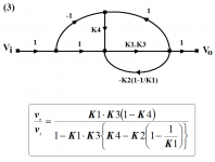
Hawksford suggests, on page 3 here, that the sensitivity of the error cancellation loop might be sensitive to ''alignment errors'', and proposes the introduction of yet another loop to ameliorate this sensitivity.
For continuity, this introduced below as summer S3 in a modification of the block diagrams previously discussed.
Attachments
traderbam said:Jan, it wasn't an offer but I am pleased to be asked and will review your work to the best of my ability. Email me when you are ready. Brian
OK, on the assumption all stays between the two of us, it's a deal!
Jan Didden
Nixie said:
So then the question is, what comprises the other?
<snipped>
Bob Cordell said:
You're asking the right questions.
While I say that THD-20 is very important, and that a full IM spectral analysis is more important, these alone appear not to tell the whole story. Again, just because they don't tell the whole story, don't throw them out. These are static distortion tests on the lab test bench, much like most of the other proposed tests. I generally like to have very low THD-20, as long as it is not done at the expense of other performance, because it is harder for other distortions, like crossover and high-order IM, to sqeek through in a well designed amp where THD-20 is very low. It is also true that this approach may unfairly penalize more benign types of distortion like second and third order.
But if THD-20 and related traditional distortions told the whole story, why would things like capacitors and cables make a difference? Part of the answer lies in amplifier misbehavior that is not caught on the test bench, either because it is not stimulated there or because the loading is too benign. Power supply related shortcomings will often not show up on the test bench. EMI susceptibility may often not show up on the test bench. Parasitic oscillation bursts may often not show up on the test bench. Thermal distortions, to the extent that they are an issue, may often not show up on the test bench. Clipping behavior and protection behavior into real speaker loads will not show up on the test bench. The list goes on...
Bob
Surely at least some of the following has already been done(?).
It seems like the Error Correction idea should be able to lead to a test instrument that could extract ALL types of distortion, for examination and additional processing.
The proposed "Error-Measuring" instrument could have two inputs, which could be connected in parallel with the input and output of any system or subsystem. It could have manual and/or automatic control systems to adjust-out the differences in average amplitude and DC offset, and to compensate for the time-delay(s) through the system. Then it would subtract the adjusted output from the input. And voila! All of the distortion, and only the distortion, would be the output.
It should be able to provide certain types of test signals, for the system-under-test's input, but should also be able to work "passively", when external input signals are present.
If done "right", it should be usable on many levels; signal transmission through basic materials, individual electronic components, sub-circuits, individual units, the entire audio chain, non-audio systems of many types, and probably much more. (Heck, maybe we could put a 3-D mouse or similar on a microphone, wave it around, and automagically make a 3-D map of speaker or room distortion characteristics. ;-)
With additional time and frequency domain processing, lots of types of information should be able to be derived from the output.
"While I'm at it", we might as well have the error-measuring instrument also be able to try to automatically derive an optimal correction signal, and, optionally, add it into the system-under-test's input. (Perhaps this could also be used to compensate-out some of the non-linearities in other measuring devices in a measurement chain, such as, just as a trivial example, a microphone that's used to measure speaker characteristics, either with a corrective "real-time" signal, or, in post-processing.) [Of course, the instrument would probably need to be 10X faster and better than the systems it would test, especially if real-time compensation was attempted. Or... just digitize everything and use a built-in delay.]
Perhaps the proposed instrument could also be used to help compile a digital library of distortion models of components and/or systems, which could be used for simulation and/or "real-time" applications.
I guess such a system might even also be able to derive enough information to enable it to attempt to provide optimal transfer functions, or digital algorithms, for the correction of some of a system-under-test's response characteristics. :-o
Ha!
Who wants one?!
- Tom Gootee, 08DEC2006
(Sorry. My imagination was getting a little rambunctious.)
-
See http://www.angelfire.com/ab3/mjramp/ for someone that has done extensive work comparing input and output.
Bill
Bill
There's also an explanation of nested feedback and "error correction" at Bill's link. http://www.angelfire.com/ab3/mjramp/errorfb.html
gootee said:
Surely at least some of the following has already been done(?).
......
Perhaps the proposed instrument could also be used to help compile a digital library of distortion models of components and/or systems, .....
What you describe is basically known as the "null test".
A couple of years back I proposed something on this lines and even made some simulations.
Probably an interesting result, apart from valuable information regarding distortion modes - could be to find correlations between anomalies "signatures" and perception subjective evaluations.
Research on this area probably is being done though I am not aware of it, and involves some moderate resources.
Rodolfo
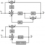
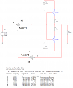
Continuing from here, the posted figure in that post is in error.
The corrected version is given below.
Noting that at balance |K2| and |K3| here (from this post) must be unity for error cancellation, it becomes evident from the transfer function below that the value of K4 is irrelevant, as this transfer function being equal to unity only depends on |K2|=|K3|=1
The corrected version is given below.
Noting that at balance |K2| and |K3| here (from this post) must be unity for error cancellation, it becomes evident from the transfer function below that the value of K4 is irrelevant, as this transfer function being equal to unity only depends on |K2|=|K3|=1
Attachments
Bob Cordell said:
Along that same line does anybody have a decent-priced 24-bit, 192 kHz sound card to recommend?
Bob
Hi Bob,
I use a Creative E-MU 1212m Digital Audio System but, I haven't actually tried much measureing yet

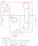
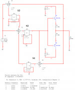
Continuing from here.
Hawksford then appears to demonstrate (pg. 4 & 5 here) that sensitivity to ''alignment errors'' is reduced by the factor 1/(1+K4).
Note that Hawksford over-simplifies his analysis by assuming an ideal input summer. This, however, may not necessarily invalidate his conclusions.
It is also noteworthy that in the process (equation 2.2) Hawksford invokes Cordell by ''decomposing'' K1 into an ideal block of unity gain plus an added error component ''Ae'', contrary to Traderbam's bizarre objections here.
Since it is clear from this analysis that the value of K4 has no bearing on the transfer function at balance, then the gain of summer S3 here can be assigned an arbitrary value.
This is done in Hawksford (fig. 5-1) by merely connecting a resistor Rs from the output of the power stage to the input of the error-cancellation loop, as shown below.
Attachments
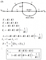
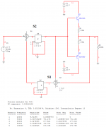
To establish, on a first-order level, whether Hawksford's conclusion may be relied upon, an unbiased emitter follower was enclosed in an ideal error correction loop courtesy of ideal summers available in Multisim.
Without the ''desensitizing'' loop, THD is near zero.
Without the ''desensitizing'' loop, THD is near zero.
Attachments
gootee said:
Surely at least some of the following has already been done(?).
It seems like the Error Correction idea should be able to lead to a test instrument that could extract ALL types of distortion, for examination and additional processing.
The proposed "Error-Measuring" instrument could have two inputs, which could be connected in parallel with the input and output of any system or subsystem. It could have manual and/or automatic control systems to adjust-out the differences in average amplitude and DC offset, and to compensate for the time-delay(s) through the system. Then it would subtract the adjusted output from the input. And voila! All of the distortion, and only the distortion, would be the output.
It should be able to provide certain types of test signals, for the system-under-test's input, but should also be able to work "passively", when external input signals are present.
If done "right", it should be usable on many levels; signal transmission through basic materials, individual electronic components, sub-circuits, individual units, the entire audio chain, non-audio systems of many types, and probably much more. (Heck, maybe we could put a 3-D mouse or similar on a microphone, wave it around, and automagically make a 3-D map of speaker or room distortion characteristics. ;-)
With additional time and frequency domain processing, lots of types of information should be able to be derived from the output.
"While I'm at it", we might as well have the error-measuring instrument also be able to try to automatically derive an optimal correction signal, and, optionally, add it into the system-under-test's input. (Perhaps this could also be used to compensate-out some of the non-linearities in other measuring devices in a measurement chain, such as, just as a trivial example, a microphone that's used to measure speaker characteristics, either with a corrective "real-time" signal, or, in post-processing.) [Of course, the instrument would probably need to be 10X faster and better than the systems it would test, especially if real-time compensation was attempted. Or... just digitize everything and use a built-in delay.]
Perhaps the proposed instrument could also be used to help compile a digital library of distortion models of components and/or systems, which could be used for simulation and/or "real-time" applications.
I guess such a system might even also be able to derive enough information to enable it to attempt to provide optimal transfer functions, or digital algorithms, for the correction of some of a system-under-test's response characteristics. :-o
Ha!
Who wants one?!
- Tom Gootee, 08DEC2006
(Sorry. My imagination was getting a little rambunctious.)
-
Actually Tom, I've already built a test instrument similar to what you describe. It is called the Distortion Magnifier. I first used it to test my MOSFET power amplifier over 20 years ago. I described the technique briefly in my MOSFET amplifier AES paper.
A more up to date and detailed description of the Distortion Magnifier is provided on my website at www.cordellaudio.com. Just look under "Distortion & Distortion Measurement", then click on "Sensitive Distortion Measurement". I soon hope to have an even more detailed description of the DM on my site.
Cheers,
Bob
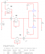
Reducing K4 from 50 to unity (with the same misalignment of 10% in the gain of summer S1) causes THD to increase by a significant amount, to 0.17%.
Thus, although the magnitude of K4 has no effect at balance, when such an imbalance exists, then it desirable that K4 be made as large as possible to desensitize the loop to the error.
Indeed, increasing the gain of K4 to 1K reduced THD (with a misalignment of 10% in the gain of summer S1) to just 0.00035%.
These results seem to confirm Hawksford's findings, and, on this basis, the circuit modification above is recommended.
Nevertheless, whether these results are replicated in practice remains to be seen.
Discuss.
Attachments
wwood said:See http://www.angelfire.com/ab3/mjramp/ for someone that has done extensive work comparing input and output.
Bill
Bill,
Thanks for the very interesting link.
- Tom Gootee
traderbam said:There's also an explanation of nested feedback and "error correction" at Bill's link. http://www.angelfire.com/ab3/mjramp/errorfb.html
Thanks for the additional interesting link.
- Tom Gootee
ingrast said:
What you describe is basically known as the "null test".
A couple of years back I proposed something on this lines and even made some simulations.
Probably an interesting result, apart from valuable information regarding distortion modes - could be to find correlations between anomalies "signatures" and perception subjective evaluations.
Research on this area probably is being done though I am not aware of it, and involves some moderate resources.
Rodolfo
Rodolfo,
Thanks for the reply. I will read your past messages about it.
- Tom Gootee
Bob Cordell said:
Actually Tom, I've already built a test instrument similar to what you describe. It is called the Distortion Magnifier. I first used it to test my MOSFET power amplifier over 20 years ago. I described the technique briefly in my MOSFET amplifier AES paper.
A more up to date and detailed description of the Distortion Magnifier is provided on my website at www.cordellaudio.com. Just look under "Distortion & Distortion Measurement", then click on "Sensitive Distortion Measurement". I soon hope to have an even more detailed description of the DM on my site.
Cheers,
Bob
Thanks, Bob! I'll have a look.
I "knew" that something along those lines had to have been done. I'm sorry to have brought it up without first doing some research.
Keep up the good work! ;-)
- Tom Gootee
- Home
- Amplifiers
- Solid State
- Bob Cordell Interview: Error Correction