Try this too. Consider the transfer functions. Fig. 3 is the equivalent Hawksford circuit with the "a" gain included. Hawksford says that to eliminate distortion caused by N the value of a must be 1.
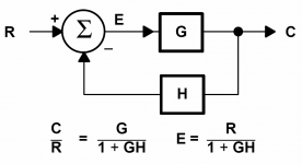
The gain of the system, closed loop as shown, is:
Vout/Vin = N/(1 - a + a.N)
The loop gain of the loop containing D is:
G = -a.N/(1 - a)
You can see that if a=1 the CL gain becomes 1 and the gain N is "cancelled" (providing N != 0). This is the result we wanted...eliminating the distortion of N. 🙂
But when you look at the loop gain, you'll see that it is infinite when a=1. In other words the system relies on infinite loop gain in order to eliminate the error in N. 🙁
Attachments

traderbam said:
Try this. Fig.1 is the Hawksford/BC system.


I am not sure about this: aren't we supposed to be subtracting the
output of N from its input?
This is key, i suspect;'could be wrong though; what think ye?
andy_c said:Oh yes. In the loop gain example I posted a while back, one of the instructions is to go into the LTSpice control panel "Save Defaults" tab and check "save device currents", "save subcircuit node voltages" and "save subcircuit device currents". This results in very big .raw files being left behind, so in the "Operation" tab I set "Automatically delete .raw files" to yes.
I think the problem is that subcircuit voltages and/or currents are being referred to in the loop gain expression but they are not being saved in the .raw file.
Does this fix it Mike?
Yes; thanks.
Forgive my confusion, but -18db loop gain is less that unity: no possibility of instability.

That's right, Mike. In fig 1 you'll notice a "-" sign on the summing node where the output signal connects. That's intended to mean that the input is multiplied by -1 before summation. A convention I picked up.
traderbam said:That's right, Mike. In fig 1 you'll notice a "-" sign on the summing node where the output signal connects. That's intended to mean that the input is multiplied by -1 before summation. A convention I picked up.
Note that you've had to implement positive feedback at the first summing node in order to make this work.
From Bob's text (pg10), you have to subtract the output to ''N'' from its input to isolate the error in ''N''.
Viz. To implement a block diagram, one has to be careful about conventions: the block diagram should have a close relationship with the resulting circutry, and conversely.
Take the usual feedback block diagram, for example: if feedback is to be negative, then error must be obtained by subtracting the signal fed back from the input, otherwise positive feedback ensues; see below:
Attachments
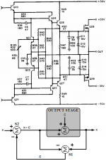
Now, compare Bob's description with the corresponding figure below:
Note that Bob's circuit uses common emitter transistors (Q22 and Q23) for S2, which necessarily inverts ''e'', as required to drive the output stage.
Here the output stage, being a source follower, is modeled as having exactly unity gain with an error voltage e(x) added.
This error represents any departure from unity gain,whether it is a linear departure due to less than unity gain, a distortion due to transconductance non-linearity or injected errors like power supply ripple.
A differential amplifier, represented by summer S1, merely subtracts the output from the input of the power stage to arrive at e(x).
This error signal is then added to the input of the power stage by summer S2 to provide that distorted input which is required for an undistorted output.
Note that Bob's circuit uses common emitter transistors (Q22 and Q23) for S2, which necessarily inverts ''e'', as required to drive the output stage.
Attachments

traderbam said:
Try this. Fig.1 is the Hawksford/BC system. Fig. 2 is the exact same system drawn in a different way. The two are equivalent. That "strange result" you see is not strange at all...your sanity is not in question. You were measuring the loop gain in path D. This is the path that includes the output device - the device that we are trying to "correct".
Good explanation.
Bob
mikeks said:Now, compare Bob's description with the the corresponding figure below:
This is correct also; just depends on how you sprinkle around your pluss's and minus's and how you use your semantics. I may have been a little loose with semantics when I said "added to the input". The diagram is correct.
Bob
forr said:I couldn't download the file whatever the method.
It crashed Firefox twice.
Hi forr,
If you send me an email, I can email you the zip file. I tried emailing you through the forum, but I can't see a way to do an attachment using that system.
The download worked okay for me using Firefox, so I'm not sure what's wrong. Maybe there are multiple servers and one of them has a corrupt file?
Andy
mikeks said:Forgive my confusion, but -18db loop gain is less that unity: no possibility of instability.
Consider an output stage that's misbehaving a bit. Let's say there's a lot of output devices in parallel, such that the output stage has a large nput capacitance. Now assume that the output stage is driven from a circuit whose output inductance is not negligible. Then there's the possibility of peaking in the combined frequency response of driver and output stage. Along with that, there can be rapid changes in the phase vs frequency of this transfer function near the frequency response peak. Let's say there's a 6 dB peak. Now assume this is all hooked up with an error correction diff amp having infinite bandwidth. The error correction will try to force the overall gain to 1, so at the frequency of the response peak of the output stage, the error correction output signal will become larger as it tries to reduce the gain. This implies an increase in loop gain magnitude, together with its phase not being well controlled.
traderbam said:
Try this. Fig.1 is the Hawksford/BC system. Fig. 2 is the exact same system drawn in a different way. The two are equivalent. That "strange result" you see is not strange at all...your sanity is not in question. You were measuring the loop gain in path D. This is the path that includes the output device - the device that we are trying to "correct".
I have a (Dutch) patent on fig 2....
Jan Didden
Jan, you surely have control of all amplifier distortion in Holland! 😀
I was looking at the European patent site but couldn't find your name in the search. I went to the Dutch country page but it was..err... double-dutch to me.
I was looking at the European patent site but couldn't find your name in the search.
I went to the Dutch country page but it was..err... double-dutch to me.janneman said:
I have a (Dutch) patent on fig 2....
Jan Didden
Hi Jan,
Can we get a look at that patent?
Thanks,
Bob
traderbam said:Jan, you surely have control of all amplifier distortion in Holland! 😀
I was looking at the European patent site but couldn't find your name in the search.
Yeah. Want to keep your secrets, write them in Dutch 😀 .
It was documented in my aes preprint 4597:
Novel Feedback Topology Obviates the Need for High Loop Gain
A novel feedback topology is presented, differing from 'classical' feedback by an additional feedback term, inversely proportional to the open-loop transfer function. The result is the elimination of the open-loop transfer function from the closed-loop equation, without requiring high loop gain. An example circuit, implemented with simple means, is discussed, showing a distortion reduction of several orders of magnitude.
Preprint Number: 4597 Convention: 103 (August 1997)
Author: Didden, Johannes M.
The file is too big to attach, I'll chop it up and paste tomorrow.
Jan Didden
😛Yeah. Want to keep your secrets, write them in Dutch
Jan, at the risk of compromising your secrets...do you agree that fig 2 is equivalent to fig 1?
This is important because this equivalence will lead me to prove that the original Hawksford system, without feedforward, is a conventional NFB loop and therefore the implementation of it can be greatly simplified. Not least of the simplifications is to remove the need for the balancing of driver feedback and output feedback signals. It will also reveal that this is indeed a high feedback system in disguise and so, contrary to Hawksford's statement in his paper, it is no refuge at all for those who wish to avoid high levels of NFB.
traderbam said:😛
Jan, at the risk of compromising your secrets...do you agree that fig 2 is equivalent to fig 1?
This is important because this equivalence will lead me to prove that the original Hawksford system, without feedforward, is a conventional NFB loop and therefore the implementation of it can be greatly simplified. Not least of the simplifications is to remove the need for the balancing of driver feedback and output feedback signals. It will also reveal that this is indeed a high feedback system in disguise and so, contrary to Hawksford's statement in his paper, it is no refuge at all for those who wish to avoid high levels of NFB.
Traderbam,
Firstly, my secret is not really a secret. After my patent was granted, I discovered that in 1953 (!) a guy called Miller, ostensibly the son of the Miller cap guy, basically did the same with tube amps. I have an article from that year in, I think Audio Craft, discussing it.
In 1999 or therabouts I contacted Ed Cherry and he convinced me that my 'invention' was known already a long time and actually documented in his course notes. He furthermore drew my attention to the class of null-networks of which my circuit and also Hawksford's are members. Their main drawback is that they need specific tuning ratios in resistors or gain blocks or whatever to null the error. That is one difference with 'normal' nfb where ratios are not critical but the error cannot be nulled.
If you read my aes pp you will see that at the time I thought that the crucial difference between classical nfb and my new topology was that in nfb you have a feedback ratio that is independent of the ol gain (just the ratio of the fb resistors) while in the new topology the fb ratio contains the inverse of the ol gain and thus is able to null the error. I believe that the Hawsford scheme has this too, but I haven't had the time yet to determine if your fig 1 and fig 2 are actually equivalent.
Edit: One way to see if Hawksford is a high fb in disguise is to remove it from the circuit. You can easily disable a Hawksford EC by removing the feedback to the input summer. If you do, the system continues to work almost unchanged, as the ol gain and cl gain (to a first order) are the same. There is no 'hidden' feedback that uses excess loop gain to decrease the errors because there IS NO excess gain. So, there is more to Hawsford's scheme than just a clever rearrangement of high nfb.
Jan Didden
traderbam said:
Try this. Fig.1 is the Hawksford/BC system. Fig. 2 is the exact same system drawn in a different way. The two are equivalent. That "strange result" you see is not strange at all...your sanity is not in question. You were measuring the loop gain in path D. This is the path that includes the output device - the device that we are trying to "correct".
Traderbam,
I believe indeed that fig 1 and fig 2 are equivalent.
If we define Ve as the input to the N-block, in both cases we see by inspection that :
Ve = Vi + Ve - Vout so Vi = Vout provided N is not zero.
I'm still not sure what that buys you, though. You have, in fig 2, introduced a classical global fb loop, but balanced by a positive feedback loop. So, I think you take the curve a bit too close in saying that therefore this is equivalent to high feedback. It's the resulting effective feedback that's important. Gerald Graeme of former BB fame has written extensively about this; you may be aware of that?
Note to moderators: Maybe the power supply discussion as initiated by Bob should be split off in a separate thread?
Jan Didden
- Home
- Amplifiers
- Solid State
- Bob Cordell Interview: Error Correction