Bob Cordell said:I certainly don't have the time or energy to get involved in a debate with you.....
Please accept my abject apologies for thus imposing on your ''time and energy''.
I shall desist forthwith.
Bob Cordell said:Also, being referred back to a bunch of equations in a prior post that may or may not be correct or be based on proper assumptions and analysis just doesn't do it for me.
Cheers,
Bob
If you can demonstrate how and where Hawksford's ''bunch of equations'' here are incorrect, i would be eternally grateful.

You do accept, of course, that these are Hawksford's equations and not mine?

Further, i find it curious that you now suggest that these equations may be incorrect when it is obvious that your EC-loop designs scrupulously adhere to said equations.
I can only assume you don't have a response to this query, and that your abdication is in some circuitous way an acceptance that your ''analysis'' is incorrect after all; thank you for your time nevertheless.
Bob Cordell said:People will remember your explanation much better than your equations. We are listening.
On the contrary, Bob, it's your explanation we are waiting for.
My explanation has hitherto not been disproved by you or anyone else.
Bob Cordell said:Then we can have a discussion about it, put some numbers on it, and perhaps learn something.
I think I'll take a leaf from your book of etiquette:
I certainly don't have the time or energy to get involved in a debate with you...
mikeks said:
Please accept my abject apologies for thus imposing on your ''time and energy''.
I shall desist forthwith.
If you can demonstrate how and where Hawksford's ''bunch of equations'' here are incorrect, i would be eternally grateful.
You do accept, of course, that these are Hawksford's equations and not mine?
Further, i find it curious that you now suggest that these equations may be incorrect when it is obvious that your EC-loop designs scrupulously adhere to said equations.
I can only assume you don't have a response to this query, and that your abdication is in some circuitous way an acceptance that your ''analysis'' is incorrect after all; thank you for your time nevertheless.
OK, Mike, sorry I ruffled your feathers. I am responding, and I do need to eat some crow for some of my own confusion. I apologize.
Here is where I got it wrong: I was looking at the functionality of Q5 and Q6 in the wrong way in regard to the issue that was at hand. Specifically, I was talking in terms of Q5 and Q6 amplifying the difference of the voltages between their bases when I referred to the 27 ohm emitter degeneration resistors and the effective tail resistance of about 165 ohms. While it does act as a differential amplifier in that mode and from that perspective, that view was not the relevant view.
The relevant view is that these transistors are differencing what comes in at the emitters with what comes in at the bases. From that way of looking at it, for sure, topologically, they don't form a traditional differential amplifier. I guess this is what you referred to that you had been struggling with. Now I see what you were complaining about, and I apologize for not seeing that sooner.
However, the linearity behavior of the pair of Q5 and Q6 is still essentially like that of a differential pair. I don't know, but we may still have some disagreement here. The point is this: let's first assume that transistor beta is high. The gain of the stage to differences is mainly determined by that 165 ohms (parallel combination of R11 & R12) in series with the combined effective resistance of the 27 ohm emitter resistors and re=1/gm of each of the Q5 and Q6 legs for current flow. The main source of nonlinearity in this arrangement is the variation of gm of Q5 and Q6 with signal. But notice, as the signal at the junction of R13 and R14 goes negative, Q5 conducts more and its gm increases, but Q6 conducts less and its gm decreases. These two effects tend to oppose each other to first order. That is the differential amplifier-type action I was referring to. This means that the current through the combination of R11 and R12 will remain fairly linear and find its way back to the collector circuits of Q5 and Q6 in an amount that is pretty linear.
Anyway, I apologize for adding confusion to the mix.
Cheers,
Bob
Mike,
I do still look forward to your specific explanation of the nonlinearity that you assert the EC transistors suffer as a result of the thermal feedback used for thermal bias stability.
With regard to the existence or non-existence of positive feedback in the EC circuit, I should never have used that analogy and should never have re-opened that wound. For that we will have to agree to disagree. Perhaps it is just the way one looks at it, and maybe both positions are right when viewed in the correct context. My position remains that there is an inner positive feedback loop, as Vanderkuy and Lipshitz pointed out, but I will not re-open that debate.
Cheers,
Bob
Bob Cordell said:My position remains that there is an inner positive feedback loop, as Vanderkuy and Lipshitz pointed out, but I will not re-open that debate.
Cheers,
Bob
That is also my position, as indicated here; I do not, however, accept that this necessarily gives ''infinite'' loop gain, as stated by some.
mikeks said:
That is also my position, as indicated here; I do not, however, accept that this necessarily gives ''infinite'' loop gain, as stated by some.
Agreed!
Bob
mikeks said:
Somehow i remain unconvinced that thus cooking your EC loop transistors has no effect on the linearity of the loop.
After all, this is responsible for the non-linearity occasioned by the dreaded thermal feedback in monolithic op. amps.
Bob Cordell said:
Mike, I am surprized that you are unfamiliar with the use of complementary transistors to form an emitter-coupled differential pair, as opposed to the usual same-sex differential pair. The key to linearity in a differential pair is that the change in gm with signal swing in one transistor is accompanied by a change in the opposite direction of the gm in the other transistor, providing a first-order cancellation of the net change in gm with signal swing, and thus a net major reduction in incremental gain with signal swing, and thus a net major reduction in distortion, particularly odd-order. This behavior of gm in the two transistors is the same whether the differential pair transistors are of the same sex or not.
In my circuit, Q5 and Q6 are just like a same-sex differential pair with 27 ohm degeneration resistors in each emitter. As the current in Q5 increases, for example, the current in Q6 decreases, giving the first-order cancellation in gm variation effect as noted above. The equivalent "tail" resistance can be thought of as comprising the parallel combination of R11 and R12, for a net equivalent tail resistance of about 165 ohms.
Cheers,
Bob
Bob,
Agreed, the distortion cancellation in complementary circuits
compared to same sex differential is similar but -
a) slightly less effective due to N / P channel device mismatch
compare to same sex
b) will reduce even order in proportion to the matching of devices.
The more matched they are the more even order cancellation.
c) with an almost exactly matched same sex pair and very ideal
devices the even order distortion reduction can be 20dB or more.
A good example of this is matched transistors such as LM394 etc
d) A good example of gross mismatch in compliments is small
signal Jfets such as 2sk170 / j74. Complementary diff pairs and
followers of these devices still seem to have large even order
domination.
I'm not sure how much of this you can find by simulation, the
devices appear to be too ideal. I have gathered the data by
measuring real devices in circuits.
cheers
Terry
Terry Demol said:
Bob,
Agreed, the distortion cancellation in complementary circuits
compared to same sex differential is similar but -
a) slightly less effective due to N / P channel device mismatch
compare to same sex
b) will reduce even order in proportion to the matching of devices.
The more matched they are the more even order cancellation.
c) with an almost exactly matched same sex pair and very ideal
devices the even order distortion reduction can be 20dB or more.
A good example of this is matched transistors such as LM394 etc
d) A good example of gross mismatch in compliments is small
signal Jfets such as 2sk170 / j74. Complementary diff pairs and
followers of these devices still seem to have large even order
domination.
I'm not sure how much of this you can find by simulation, the
devices appear to be too ideal. I have gathered the data by
measuring real devices in circuits.
cheers
Terry
Terry,
These are very good points. It turns out that the biggest thing that is typically mismatched in bipolars, especially from one sex to another, is current gain and Vbe. These are not what really matter in this application, as long as current gain is high. The key contributor to distortion, and the parameter that wants to be matched best, is gm. Fortunately, the behavior of gm in bipolar devices is mainly governed by physics, so matching tends to be natural. One departure from gm that can sometimes not be matched and may come into play is the resistive component in either base resistance or emitter resistance, but these are usually pretty negligible contributors to mismatch that matters in this circuit.
Your point about mismatch among different-sex JFETs is well-taken. I also agree that simulation results can often yield unreasonably ideal conditions.
Cheers,
Bob
Massive symmetric feedback
I have been following this thread with interest, but I just couldn't help but wonder if simply applying a lot of symmetric feedback with a fully differential opamp like the THS4131 could accomplish the goal of very low distortion.
Here is a simulation I whipped up today which looks pretty promising... In fact the numbers look so good I really am not sure I trust the simulation...
The input is balanced, and the output is symmetrical(bridged).
Any thoughts?
I have attached the LTSpice project files.
Cheers!
Russ
Attachments
Re: Massive symmetric feedback
Here's another example of such a configuration. Or this one.
It reduces distortion as the feedback error appears in common mode on the opposite side. And you can get pretty low distortion. But I don't see how this relates to error correction.
Isn't this the type of chip that TI licensed Nelson Pass' 'susy' patent for?Russ White said:THS4131
Here's another example of such a configuration. Or this one.
It reduces distortion as the feedback error appears in common mode on the opposite side. And you can get pretty low distortion. But I don't see how this relates to error correction.
Re: Re: Massive symmetric feedback
Yes I am very familiar with SuSy, but I was still surprised at how well it simulates.
So, if the feedback corrects the error.... well, isn't that a form of error correction? 🙂 I was just showing that feedback applied like this could be as effective as EC.
Cheers!
Russ
Nixie said:
Isn't this the type of chip that TI licensed Nelson Pass' 'susy' patent for?
Here's another example of such a configuration. Or this one.
It reduces distortion as the feedback error appears in common mode on the opposite side. And you can get pretty low distortion. But I don't see how this relates to error correction.
Yes I am very familiar with SuSy, but I was still surprised at how well it simulates.
So, if the feedback corrects the error.... well, isn't that a form of error correction? 🙂 I was just showing that feedback applied like this could be as effective as EC.
Cheers!
Russ
Nixie said:Try simulating with not perfectly matched devices 😉
Good suggestion, and I have, I changed the Hfe, and effective Vce of the devices in the output stage(and drivers) without much change in performance.
You do need to keep the feedback resistors pretty tight, but 1% seems to do fine. .1% is of course, well, better.
Cheers!
Russ
So now how to add error correction to the Aleph-X for even better performance? 😀
The other amp I linked is 0.004% THD as it is. Would be interesting to get another 0 in there. But is it best to add EC on a differential stage separately for each side, or take error differentially, so it works best with the susy? Also, both have gain in the output stages, and people here don't seem to be interested in discussing EC on stages with gain.
The other amp I linked is 0.004% THD as it is. Would be interesting to get another 0 in there. But is it best to add EC on a differential stage separately for each side, or take error differentially, so it works best with the susy? Also, both have gain in the output stages, and people here don't seem to be interested in discussing EC on stages with gain.
Bob Cordell said:But notice, as the signal at the junction of R13 and R14 goes negative, Q5 conducts more and its gm increases, but Q6 conducts less and its gm decreases. These two effects tend to oppose each other to first order. That is the differential amplifier-type action I was referring to.
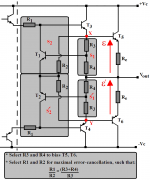
I think you'll find that the difference in potential between the bases of T1 and T2 in Hawksford's arrangement remains virtually constant.
Attachments
Bob Cordell said:However, the linearity behavior of the pair of Q5 and Q6 is still essentially like that of a differential pair.
The linearity is due to the heavy local feedback.
''Desensitizer'' continued.
By comparing Hawksford's implementation with the block diagram here it becomes apparent that Hawksford is in flagrant error, for merely connecting a bootstrap resistor from the output to the input of the output stage gives the opposite of the desired effect.
This is because the signal fed back from the output (with respect to the input) by the extra loop must degenerate the signal applied to the output stage (summer S4); the bootstrap resistor, on the other hand, is regenerative.
I have designed an active implementation, consistent with maximising K4's gain, the desirability of which has been amply demonstrated.
Although it entailed a significant increase in component-count, the circuit was found to considerably reduce sensitivity of the EC loop to component tolerances. 😎
Interested parties are incouraged to develop their own interpretations of the model.
mikeks said:
I think you'll find that the difference in potential between the bases of T1 and T2 in Hawksford's arrangement remains virtually constant.
That's true, but pumping current in and out of the joined emitters results in the complementary changes in gm that I was referring to.
Bob
mikeks said:
Yes, this is largely true. However, any small departures from linearity are the result of gm changes, and the fact that these gm changes are complementary in nature further improves the linearity.
Bob
- Home
- Amplifiers
- Solid State
- Bob Cordell Interview: Error Correction