ingrast said:
A vivid appreciation is not very difficult anyway.
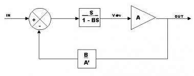
Assume for a moment A'=Ao, where Ao is a constant (eg. nominal, real amplifier gain).
Rodolfo
"A vivid appreciation is not very difficult anyway. ..."
... Indeed! LOL!
Rodolfo, I do remember from some time back that you were interested in output stages with gain as I also have been for over 30 years. The refinement in your model to allow for such implementations is a worthwhile consideration. I also see that your A and A' allow for gain mismatch due to tolerances in real hardware. Nice work!
There is discussion in the Power Supply thread about extra taps on the transformer, rectifiers, and caps in order to provide a higher supply voltage to the front end circuits for designs with unity gain output stages. An output stage with gain, even simply 2X, is a much cleaner and cost effective approach, since all that's needed is a simple Zener or pass regulator to the front end.
A minor point is that your S1 and S2 symbols are shown with a multiply operator, X.
One point that is not clear to me, is your use of the S gain block in the forward path. You write: "In Fig. 3 we have included block S to denote some form of active network must be present in order to be able to adjust for near cancellation."
If I read you correctly, that it is for adjustment of the error null, I'd expect it to be placed in the error feedback path, to the negative input of S1. I read the paper quickly, perhaps I missed something. I'm also not completely clear on the implied implementation assuming you had some specific hardware in mind.
I notice that 1/A' > 1 for output stages with less than unity gain which suggests an active block rather than a passive divider. Moving it to the S2 negative input path, in these cases, again provides for A' < 1 and therefore a passive network. A minor point, probably does not impact the analysis.
I agree completely with your points considering error correction as compared to traditional negative feedback.
Pete B.
PB2 said:
"A vivid appreciation is not very difficult anyway. ..."
... Indeed! LOL!
Pete, thank you for your encouraging comments !!!
...... I also see that your A and A' allow for gain mismatch due to tolerances in real hardware. Nice work!.....
In fact it underscores a more important fact, A is the actual amplifier complex nonlinear transfer function, while 1/A' is usually a passive attenuator.
A minor point is that your S1 and S2 symbols are shown with a multiply operator, X.
Agree it may be misleading, but actually this notation is frequently used in the literature.
One point that is not clear to me, is your use of the S gain block in the forward path. ......
If I read you correctly, that it is for adjustment of the error null, I'd expect it to be placed in the error feedback path, to the negative input of S1. .......
Pete B.
S is meant to represent the fact the summing node usually is an active subsystem, so I segregated the ideal summer from the implicit active device.
Note in fact the "cancellation" condition is 1/S - B = 0, or perhaps more clearly B.S = 1 meaning in fact the active role may be played either by B or S. It is simply a matter of convenience to assign it to S but the condition is not restrictive.
With respect to "null" adjustment, I do it with a 10 turn pot in the feedback path (where B belongs roughly, but actual circuit topology is different yet functionally equivalent).
Rodolfo
PS:
I purchased the Lipshitz-Vanderkooy paper through the AES and will comment here if I deem interesting (to contribute, that is).
ingrast said:
In fact it underscores a more important fact, A is the actual amplifier complex nonlinear transfer function, while 1/A' is usually a passive attenuator.
Yes, the challenge of real design work. I wondered when someone would bring this up.
ingrast said:
S is meant to represent the fact the summing node usually is an active subsystem, so I segregated the ideal summer from the implicit active device.
Note in fact the "cancellation" condition is 1/S - B = 0, or perhaps more clearly B.S = 1 meaning in fact the active role may be played either by B or S. It is simply a matter of convenience to assign it to S but the condition is not restrictive.
....
Rodolfo
Yes, this was what I thought, makes sense.
Thank you Rodolfo,
Pete B.
I just took a look at Bob's paper mainly at the schematics, it's been over 20 years since I first read it. I can understand using numerous complex features for a journal paper, however that's quite the component count!
I have to wonder how something like Nelson's FET Citation mod would respond to EC, or the Hafler designs. I expect it would work just fine.
Any connection, Bob between your work and the Hafler power amp designs? They probably at least read your paper.
Pete B.
I have to wonder how something like Nelson's FET Citation mod would respond to EC, or the Hafler designs. I expect it would work just fine.
Any connection, Bob between your work and the Hafler power amp designs? They probably at least read your paper.
Pete B.
Actually if that system had gain greater than unity as you've suggested, then error applied to the power stage (at its input) would be greater than that extracted.traderbam said:You may have noticed that the loop gain of 27dB is not the "infinity" that Hawksford's model requires for perfect correction (which is impractical). I would like to see what the loop gain is of the full Spice model plotted against frequency to confirm this finding.
Conversely, if the system generates attenuation (transmission less than unity), then error applied to your power stage would be less than the error extracted.
Self-evidently, in both instances, you cannot have error cancellation, by any stretch of imagination.
This is why, as Bob indicated in his paper, it may be necessary to include means of adjustment to optimise system performance.
If, on the other hand, your output stage possesses a well defined gain greater than the nominal unity as i have discussed here,, and used, for instance, in the Marantz SM 17 power amplifier, then the system's transmission must necessarily apply the same gain to the extracted error before introducing it to the input of your power stage.
It is elementary stuff such as this that seems to escape ''experianced'' PB2-type folks.
ingrast said:In fact it underscores a more important fact, A is the actual amplifier complex nonlinear transfer function, while 1/A' is usually a passive attenuator.
No one can reasonably argue against the obvious notion that the quantities at issue are complex (or vary as a function of frequency, and may even do so non-linearly at the limit of their performance-envelopes).
Now, if your (1/A'), which you previously said was non-essential, is an attenuator (passive at that, i'll be bound!), then it really should be lumped together with one or both blocks that must exist if non-ideality is accommodated.
This, i suspect, would invalidate your selected point of analysis (between the (1/A') block and S2).
Anyway, Rodolfo, i look forward to reading your paper. I am certain it will also be of benefit to members here.
By the way, did the THD performance of your prototypes at HF approach or surpass that of other designs using this method?
Moreover, did you identify any evidence of local instability as you attempted to tweak the error cancellation loop for least THD at HF?
Attachments
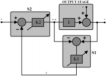
mikeks said:If, on the other hand, your output stage possesses a well defined gain greater than the nominal unity as i have discussed here, and used, for instance, in the Marantz SM 17 power amplifier, then the system's transmission must necessarily apply the same gain to the extracted error before introducing it to the input of your power stage.
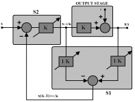
In fact, as demonstrated below, if the output stage is designed to have a nominal non-inverting gain of five, then it may (invoking the Cordell approach) be assumed to consist of an ideal gain block providing the exact gain of five plus added error.
If summer S1 provides unity-gain, then the system (step #01 below) must provide a gain of five before summer S2 provides subtraction.
Attachments

To continue...
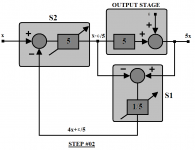
This, obviously, is rather inelegant, and may be circumvented by merely using the simple rules of block diagram manipulation to give step #02 below.
Note the similarity in structure to that previously obtained with a unity-gain output stage.
In this case, however, since S1 provides attenuation while S2 provides amplification, the THD of the later in particular is likely to compromise error cancellation more significantly than is the case with unity gain summers.
Discuss.
Attachments
Mike wrote:
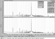
Andy_c could you measure the loop gain of the spice model for us?
Gain 27dB, phase 180. All these systems depend on high loop gain to achieve error correction, because they are all equivalent to a conventional NFB topolgy. The only distinction is whether the excess loop gain is generated by a regular gain block or by a positve feedback loop. Bob's circuit, in practice, will probably be tuned for a higher excess gain than the simplifed model I posted.Actually if that system had gain greater than unity as you've suggested, then error applied to the power stage (at its input) would be greater than that extracted.
Andy_c could you measure the loop gain of the spice model for us?
mikeks said:
........
Now, if your (1/A'), which you previously said was non-essential, is an attenuator (passive at that, i'll be bound!), then it really should be lumped together with one or both blocks that must exist if non-ideality is accommodated.
Michael,
Perhaps I was not clear enough in previous posts.
The diagram selection was dictated by the desire to convey in the most sugestive form, functions performed by different parts while being general enough. I suspect all feedback error correction topologies can be proved to be either particular cases of the one I posted, or functionally equivalent. At least a single OpAmp configuration which I actually use in my prototypes I proved to be equivalent and simulated and worked as predicted.
The reasoning behind error correction - and what sets it apart from cannonical negative feedback - is to start by measuring the actual error generated by a nonideal transfer - and only then to insert it in appropriate way so as to ideally cancel it altoghether.
To measure transfer error, one also wants to compare magnitudes of similar range. While it is perfectly acceptable to make for example A'=1 no matter the nominal amplifier gain A, I find more satisfying to first scale back the output signal to the input level range before performing the actual substraction.
Elegance nonwithstanding, this scheme has a couple of interesting benefits.
First, it makes better use of the comparator (in this case S2) dynamic range because its output will be only the error signal instead of the error signal superimposed to a (probably large) clean signal.
Second, it allows for different than unity gain amplifier A and actual setting of system gain by the value of A'. This is a desirable flexibility I should not chose to do without.
This, i suspect, would invalidate your selected point of analysis (between the (1/A') block and S2).
By definition loop gain can be computed anywhere along the loop yielding the same result.
By the way, did the THD performance of your prototypes at HF approach or surpass that of other designs using this method?
I cannot claim beyond what I have actually measured within my capabilities. A 1 KHz test signal of 0.002% THD quality is reproduced with equal 0.002% level THD (60W / 4 ohm). This measurement is made simultaneously through left and right channels of an Audigy II USB external box, both input levels equal (amplifier output attenuated as required).
As reference, a test amplifier built with an LM3886 in 20 dB gain configuration, when measured in identical conditions shows obvious input/output differences. In fact I checked the LM3886 but as plant within the error correction scheme, and could both make it work stably (albeit with some difficulty) and yield better performance.
Sensitivity attenuation is expected to deteriorate at least at 6 dB/oct rate so I do not know for the time being for example the performance level at 20KHz. Ther is though ample room for improvement in the power stage design, which sets the starting nonlinearity level to be attenuated by error correction.
Moreover, did you identify any evidence of local instability as you attempted to tweak the error cancellation loop for least THD at HF?
Once a very basic lead compensation is included, adjustment allows for a smooth minimum of harmonics at the optimum point, with instability only begining to hint well beyond it, and when harmonics have again increased notoriously. This behavior is also to be expected but is of no interest. The minimum is fairly stable and non-critical.
Rodolfo
Attachments
Note
You may have noted in the previous spectral analysis, the amplifier output (lower trace) happens to yield lower THD than the input (higher trace). No paradox here, simply both input channels for the Audigy II are slightly different and this differences are beyond what can be garanteed at this price / performance level.
Rodolfo
But you have all this in fig 1 without needing S2 at all. Aren't you making it easier to implement a summing node that you don't need?First, it makes better use of the comparator (in this case S2) dynamic range because its output will be only the error signal instead of the error signal superimposed to a (probably large) clean signal.
Second, it allows for different than unity gain amplifier A and actual setting of system gain by the value of A'. This is a desirable flexibility I should not chose to do without.
ingrast said:
By definition loop gain can be computed anywhere along the loop yielding the same result.
The true loop gain in a multiple loop system with a common node can only be correctly ascertained if the test point is chosen so that were the circuit broken at this point all feedback loops would be simultaneously disconnected.
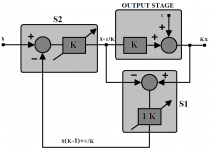
in general (continuing from here), in respect of an output stage with a reasonably well defined, arbitrary nominal gain K (which, of course, may be unity), the following applies:
Attachments
ingrast said:First, it makes better use of the comparator (in this case S2) dynamic range because its output will be only the error signal instead of the error signal superimposed to a (probably large) clean signal.
Rodolfo
Rodolfo,
S2's dynamic range may be optimised by collocating your (1/A') block, or, indeed, any other conceivable adjustments, into the gain/non-ideality represented by the block at the ideal S1's output here.
I think Rodolfo is right that the loop gain of a loop is whatever it is when broken, regardless of any other loops. I think what you are talking about is measuring a single loop without contribution from other loops, which requires breaking all the other loops before doing the measurement.The true loop gain in a multiple loop system with a common node can only be correctly ascertained if the test point is chosen so that were the circuit broken at this point all feedback loops would be simultaneously disconnected.
Rodolfo,
Here is my equivalent diagram of your Fig.3. What I want to know is why it is better, from an implementation point of view, to use fig 3 topology?
Attachments
ingrast said:
While it is perfectly acceptable to make for example A'=1 no matter the nominal amplifier gain A, I find more satisfying to first scale back the output signal to the input level range before performing the actual subtraction.
Rodolfo
Rodolfo,
Assuming you are referring to a unity gain stage, there is no need to ''to first scale back the output signal to the input level range before performing the actual subtraction'', since, in practical output stage, gain is, in fact, always less than unity.
Now, were this assumption untrue, then in any event it would be accommodated in your adjustable 1/K block, which, after all, is part of S1 here.
Indeed, using the simple rules of block diagram manipulation given here, it is self-evident that the former is equivalent to the following:
Attachments

- Home
- Amplifiers
- Solid State
- Bob Cordell Interview: Error Correction