Re: Re: Re: Error Correction Sensitivity
Bob,
Based on your postings on this forum I would expect you to take the simulations results with a little bit of salt. Have you ever build an EC OPS with a THD of 15ppm open loop? Do you think this is even possible in practice?
Anyways, I'm taking THD20, apparently you are looking at 1KHz. BTW, I measured our OPS THD20 before EC, it is 1.1%. Which makes the EC contribution to bring the THD20 to a measured 90ppm, on top of my head, a little over 40dB.
At 1KHz the THD before EC is measured at 0.68% while after applying EC is down to a measured 30ppm which means an EC contribution of, again on top of my head, some 48dB.
I must be dense today, but I don't see any significant (relative) difference to your conclusions. Except for the balancing method, for which I am having some difficulties un following your definition of 1% tolerance or precision. I will try harder tomorrow.
Bob Cordell said:
Ovidiu,
There is something not right here. I don't think the results are matching, maybe off by a factor of ten.
In my post above, the open loop output stage with EC with balance off by 1% was yielding THD of 0.00155 %, which is only 15.5 ppm. This is way under 100 ppm.
Please also understand that the trim location I use is a single resistor in series with the junction of the two emitter resistors of the error pair. The optimum value of this trim resistor is only on the order of 10% of the total effective resistance in the circuit at that point, so a 1% change in balance corresponds to about a 10% change in this trim resistor, so there is no big issue with available resistor value quantization.
Cheers,
Bob
Bob,
Based on your postings on this forum I would expect you to take the simulations results with a little bit of salt. Have you ever build an EC OPS with a THD of 15ppm open loop? Do you think this is even possible in practice?
Anyways, I'm taking THD20, apparently you are looking at 1KHz. BTW, I measured our OPS THD20 before EC, it is 1.1%. Which makes the EC contribution to bring the THD20 to a measured 90ppm, on top of my head, a little over 40dB.
At 1KHz the THD before EC is measured at 0.68% while after applying EC is down to a measured 30ppm which means an EC contribution of, again on top of my head, some 48dB.
I must be dense today, but I don't see any significant (relative) difference to your conclusions. Except for the balancing method, for which I am having some difficulties un following your definition of 1% tolerance or precision. I will try harder tomorrow.
Re: Re: Re: Re: Error Correction Sensitivity
Ovidiu,
But you started off your previous post by saying that my simulation results were consistent with your measurement results. Now you say to take simulation results with a grain of salt. Which is it?
Bear in mind that the purpose of my earlier post was to show the nature of the sensitivity of EC to the trim, not to show how to get an amplifier down to 1 ppm. That is why I did those simulations at 1 kHz and 9V peak.
My simulations showed that a 1% error in the balance condition will still allow EC to deliver a 40 dB improvement.
In the case I simulated, I started off with a non-EC THD-1 of 0.15%, and ended up with about 0.0015% when EC was applied with a 1% error, thus the 40 dB improvement.
Full-power and 20 kHz is a slightly different story, as is the starting point of the THD of the output stage you are using.
I'll show another post that addresses these other issues.
Cheers,
Bob
syn08 said:
Bob,
Based on your postings on this forum I would expect you to take the simulations results with a little bit of salt. Have you ever build an EC OPS with a THD of 15ppm open loop? Do you think this is even possible in practice?
Anyways, I'm taking THD20, apparently you are looking at 1KHz. BTW, I measured our OPS THD20 before EC, it is 1.1%. Which makes the EC contribution to bring the THD20 to a measured 90ppm, on top of my head, a little over 40dB.
At 1KHz the THD before EC is measured at 0.68% while after applying EC is down to a measured 30ppm which means an EC contribution of, again on top of my head, some 48dB.
I must be dense today, but I don't see any significant (relative) difference to your conclusions. Except for the balancing method, for which I am having some difficulties un following your definition of 1% tolerance or precision. I will try harder tomorrow.
Ovidiu,
But you started off your previous post by saying that my simulation results were consistent with your measurement results. Now you say to take simulation results with a grain of salt. Which is it?
Bear in mind that the purpose of my earlier post was to show the nature of the sensitivity of EC to the trim, not to show how to get an amplifier down to 1 ppm. That is why I did those simulations at 1 kHz and 9V peak.
My simulations showed that a 1% error in the balance condition will still allow EC to deliver a 40 dB improvement.
In the case I simulated, I started off with a non-EC THD-1 of 0.15%, and ended up with about 0.0015% when EC was applied with a 1% error, thus the 40 dB improvement.
Full-power and 20 kHz is a slightly different story, as is the starting point of the THD of the output stage you are using.
I'll show another post that addresses these other issues.
Cheers,
Bob
Re: Re: Re: Re: Re: Error Correction Sensitivity
The relative THD improvements are similar, that is, the dB numbers are similar. This has little to nothing to do with the absolute THD values. In these numbers, I don't see anything that is "order of magnitude" apart.
In terms of absolute THD numbers, a value of 15ppm open loop does not seem to be realistic so the whole experiment is to me questionable.
Based on your simulation results (and mine as well) and my measurements, it appears that the relative decrease in THD with EC is pretty consistent, even at different output levels and frequencies. Which is what I originally stated - and I'm sorry if that was not clear enough.
Could you define exactly what you mean by "balance condition"? Is this the Hawksford balance R1=(1-k)*R2 or it's the precision/tolerance of a resistor? When talking 1% I have in mind a resistor value, namely R2 above or R3/R4 in our design or, if memory serves, R34/R35 in your original AES paper.
Anyway, you asked some time ago for the THD values in the OPS, before EC. These are 0.68% THD1 and 1.1% THD20, both measured at full power (187W) into 4ohm, HTH.
Bob Cordell said:
Ovidiu,
But you started off your previous post by saying that my simulation results were consistent with your measurement results. Now you say to take simulation results with a grain of salt. Which is it?
The relative THD improvements are similar, that is, the dB numbers are similar. This has little to nothing to do with the absolute THD values. In these numbers, I don't see anything that is "order of magnitude" apart.
In terms of absolute THD numbers, a value of 15ppm open loop does not seem to be realistic so the whole experiment is to me questionable.
Based on your simulation results (and mine as well) and my measurements, it appears that the relative decrease in THD with EC is pretty consistent, even at different output levels and frequencies. Which is what I originally stated - and I'm sorry if that was not clear enough.
My simulations showed that a 1% error in the balance condition will still allow EC to deliver a 40 dB improvement.
Could you define exactly what you mean by "balance condition"? Is this the Hawksford balance R1=(1-k)*R2 or it's the precision/tolerance of a resistor? When talking 1% I have in mind a resistor value, namely R2 above or R3/R4 in our design or, if memory serves, R34/R35 in your original AES paper.
Anyway, you asked some time ago for the THD values in the OPS, before EC. These are 0.68% THD1 and 1.1% THD20, both measured at full power (187W) into 4ohm, HTH.
Re: Re: Re: Re: Re: Re: Error Correction Sensitivity
Ovidiu,
We are apparently talking about three different things here.
First is the amount in dB of improvement to be gained from EC. In that respect, we seem to be in agreement.
Secondly, we are talking about the EC balance condition and precision needed to get there, and the definition of percentage error in the balance condition.
Third, we are talking about the absolute percentage THD achievable in a given EC implementation.
The schematic below of the simulation I used in my earlier post may be helpful. It is a straightforward implementation of my original EC design, with D1 and D2 added to help accomodate the lower gate turn-on voltage required for the Toshiba MOSFETs to achieve the 150 mA idle current.
This circuit also shows the EC balance tweak resistor explicitly as R23. That is what to focus on. The total resistance in R23's circuit is re/2 of Q3-4, plus R5/2, plus R23, plus R11/2, ignoring any source resistance effects at the emitters of Q7 and Q8. This resistance, with re of Q3-4 about 5 ohms, adds up as follows:
2.5 + 13.5 + 18 + 135 = 169 ohms
The balance condition is that this circuit resistance wants to be one-fourth the value of R1 = 680 / 4 = 170 ohms.
As you can see, we have come very close here.
A 1% error in the balance condition is the same as a 1% error in this 170 ohm circuit resistance in the emitter circuit of Q3-4.
I was also pleasantly surprized that the EC could drop the distortion by such a large amount to such a very small value. In this case, the THD-1 of the output stage without EC was 0.15%. YMMV. Note that the sim shows an astonsihing reduction of a factor of 469 to a value of 0.00032% under the perfect balance condition. Bear in mind we are at 9 V peak into 8 ohms here and that we are at 1 kHz.
Do I believe this will happen in practice? No. But we may get closer than you think. Don't forget, your friend Edmond places a very high value on simulation results, as evidenced by his simulation-based claims about his NFB-only approach to the output stage. What is good for the goose is good for the gander.
Cheers,
Bob
syn08 said:
The relative THD improvements are similar, that is, the dB numbers are similar. This has little to nothing to do with the absolute THD values. In these numbers, I don't see anything that is "order of magnitude" apart.
In terms of absolute THD numbers, a value of 15ppm open loop does not seem to be realistic so the whole experiment is to me questionable.
Based on your simulation results (and mine as well) and my measurements, it appears that the relative decrease in THD with EC is pretty consistent, even at different output levels and frequencies. Which is what I originally stated - and I'm sorry if that was not clear enough.
Could you define exactly what you mean by "balance condition"? Is this the Hawksford balance R1=(1-k)*R2 or it's the precision/tolerance of a resistor? When talking 1% I have in mind a resistor value, namely R2 above or R3/R4 in our design or, if memory serves, R34/R35 in your original AES paper.
Anyway, you asked some time ago for the THD values in the OPS, before EC. These are 0.68% THD1 and 1.1% THD20, both measured at full power (187W) into 4ohm, HTH.
Ovidiu,
We are apparently talking about three different things here.
First is the amount in dB of improvement to be gained from EC. In that respect, we seem to be in agreement.
Secondly, we are talking about the EC balance condition and precision needed to get there, and the definition of percentage error in the balance condition.
Third, we are talking about the absolute percentage THD achievable in a given EC implementation.
The schematic below of the simulation I used in my earlier post may be helpful. It is a straightforward implementation of my original EC design, with D1 and D2 added to help accomodate the lower gate turn-on voltage required for the Toshiba MOSFETs to achieve the 150 mA idle current.
This circuit also shows the EC balance tweak resistor explicitly as R23. That is what to focus on. The total resistance in R23's circuit is re/2 of Q3-4, plus R5/2, plus R23, plus R11/2, ignoring any source resistance effects at the emitters of Q7 and Q8. This resistance, with re of Q3-4 about 5 ohms, adds up as follows:
2.5 + 13.5 + 18 + 135 = 169 ohms
The balance condition is that this circuit resistance wants to be one-fourth the value of R1 = 680 / 4 = 170 ohms.
As you can see, we have come very close here.
A 1% error in the balance condition is the same as a 1% error in this 170 ohm circuit resistance in the emitter circuit of Q3-4.
I was also pleasantly surprized that the EC could drop the distortion by such a large amount to such a very small value. In this case, the THD-1 of the output stage without EC was 0.15%. YMMV. Note that the sim shows an astonsihing reduction of a factor of 469 to a value of 0.00032% under the perfect balance condition. Bear in mind we are at 9 V peak into 8 ohms here and that we are at 1 kHz.
Do I believe this will happen in practice? No. But we may get closer than you think. Don't forget, your friend Edmond places a very high value on simulation results, as evidenced by his simulation-based claims about his NFB-only approach to the output stage. What is good for the goose is good for the gander.
Cheers,
Bob

Bob Cordell said:Forgot the schematic.
Here it is.
Bob
Bob,
One of the reasons you got such great results on the THD reduction is the use of 2N5550/2N5401 in the driver stage. Due to power dissipation reasons, this will never fly in the real world. You may want to select a pair of good TO220 devices and see how the circuit behaves.
Re: Re: Re: Re: Re: Re: Re: Error Correction Sensitivity
Have I mentioned somewhere my unconditional agreement with any simulation results, be it Edmond's, yours or mine? Am I wrong if I think friendship has nothing to do with good or bad simulations?
I recall you being quite skeptical about simulation results (especially regarding THD numbers, e.g. http://www.diyaudio.com/forums/showthread.php?postid=1223782#post1223782 ), so I was just expressing my surprise about your current trust in such.
Now that we have a common ground, I'll take a closer look to the sensitivity topic from a practical/measurements perspective and let you know. Do you think that simulations/measurements are relevant at low frequency/low output level/high load? I think the "worst case" (20KHz/full power/4ohm) would be more relevant on both THD20 absolute values and sensitivity.
Bob Cordell said:
Do I believe this will happen in practice? No. But we may get closer than you think. Don't forget, your friend Edmond places a very high value on simulation results, as evidenced by his simulation-based claims about his NFB-only approach to the output stage. What is good for the goose is good for the gander.
Have I mentioned somewhere my unconditional agreement with any simulation results, be it Edmond's, yours or mine? Am I wrong if I think friendship has nothing to do with good or bad simulations?
I recall you being quite skeptical about simulation results (especially regarding THD numbers, e.g. http://www.diyaudio.com/forums/showthread.php?postid=1223782#post1223782 ), so I was just expressing my surprise about your current trust in such.
Now that we have a common ground, I'll take a closer look to the sensitivity topic from a practical/measurements perspective and let you know. Do you think that simulations/measurements are relevant at low frequency/low output level/high load? I think the "worst case" (20KHz/full power/4ohm) would be more relevant on both THD20 absolute values and sensitivity.
hec != hoax ?
Hi Bob,
And I stick to my point of view, as this is the only one who reveals that there are stability issues and also predict exactly how much thd reduction one might expect. Although the other views might be 'valid', they don't give us any insight on these two most important aspects. Regarding the insights from the other points of view, are they helpful in any way? No, only confusing.
Moreover, HEC is error feedback. So, it's more than obvious and appropriate to look at it as a NFB system.
As for simulating a complete amplifier, why should I? Comparing the two output stages tells us anything we need to know. But I can assure you that my non-HEC OPS, combined with your front end will perform equally well and perhaps even slightly better.
(Actually I did that just that, by using Micro-Cap it's a snap 😀)
As for the frequency/phase response plot, why you ask me? You have all the tools and models to do it by yourself. Nevertheless, as I'm a really nice guy (sometimes), here they are. The 1st one with a 8 Ohm load and the 2nd one with a 4 Ohm load.
As for different gate stopper resistors, come on Bob, for a man of your stature, the answer should be quite obvious. I'll give you one hint: optical symmetry does not always coincidence with electrical symmetry.
Cheers, Edmond.
Bob Cordell said:Hi Edmond,
First, I stick to my point that multiple views of a technology like EC are valuable and provide insight. Your one-dimensional view of HEC as only negative feedback is valid, and I have never disputed that, but it is not the only valid way to look at it. Your "my way or the highway" approach is less helpful.
I know your simulations are quite good, but as far as I know, you have not shown a simulation of it as a complete amplifier showing good stability and THD below 10 ppm even.
Can you show us an ac frequency/phase response plot of your current preferred version of this output stage out to about 20 MHz? Can you also show us this plot into 4 ohms load?
I'm curious, why did you use different gate stopper resistors for your two output MOSFETs?
Cheers,
Bob
Hi Bob,
And I stick to my point of view, as this is the only one who reveals that there are stability issues and also predict exactly how much thd reduction one might expect. Although the other views might be 'valid', they don't give us any insight on these two most important aspects. Regarding the insights from the other points of view, are they helpful in any way? No, only confusing.
Moreover, HEC is error feedback. So, it's more than obvious and appropriate to look at it as a NFB system.
As for simulating a complete amplifier, why should I? Comparing the two output stages tells us anything we need to know. But I can assure you that my non-HEC OPS, combined with your front end will perform equally well and perhaps even slightly better.
(Actually I did that just that, by using Micro-Cap it's a snap 😀)
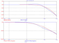
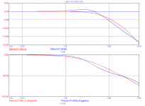
As for the frequency/phase response plot, why you ask me? You have all the tools and models to do it by yourself. Nevertheless, as I'm a really nice guy (sometimes), here they are. The 1st one with a 8 Ohm load and the 2nd one with a 4 Ohm load.
As for different gate stopper resistors, come on Bob, for a man of your stature, the answer should be quite obvious. I'll give you one hint: optical symmetry does not always coincidence with electrical symmetry.
Cheers, Edmond.
Attachments
syn08 said:
Bob,
One of the reasons you got such great results on the THD reduction is the use of 2N5550/2N5401 in the driver stage. Due to power dissipation reasons, this will never fly in the real world. You may want to select a pair of good TO220 devices and see how the circuit behaves.
Yes, I know that; I was just being lazy. Use of the Sanyo parts you use in your VAS will yield just as good performance, I'm sure. I have not yet tweaked them so they have a reasonable Vbe-IC characteristic, though. The TO-220 Toshibas you guys used would also do well there. I'll go do a sanity check, but I'm sure results will be virtually unchanged.
Bob
Re: Re: Re: Re: Re: Re: Re: Re: Error Correction Sensitivity
Lighten up, Ovidiu. I did not mean in the least that your friendship would influence your view of simulation results. Can't you take a little friendly tweak?
In fact, Edmond has been one of the ones who has led the way in showing that SPICE is better for distortion analysis than some of us thought. The intervening months, combined with excellent work that has been done on SPICE models has indeed made me much more appreciative of the value of SPICE distortion simulations. We all are entitled to change our opinions based on experience and new data, and I am quite comfortable in admitting to it.
Cheers,
Bob
syn08 said:
Have I mentioned somewhere my unconditional agreement with any simulation results, be it Edmond's, yours or mine? Am I wrong if I think friendship has nothing to do with good or bad simulations?
I recall you being quite skeptical about simulation results (especially regarding THD numbers, e.g. http://www.diyaudio.com/forums/showthread.php?postid=1223782#post1223782 ), so I was just expressing my surprise about your current trust in such.
Now that we have a common ground, I'll take a closer look to the sensitivity topic from a practical/measurements perspective and let you know. Do you think that simulations/measurements are relevant at low frequency/low output level/high load? I think the "worst case" (20KHz/full power/4ohm) would be more relevant on both THD20 absolute values and sensitivity.
Lighten up, Ovidiu. I did not mean in the least that your friendship would influence your view of simulation results. Can't you take a little friendly tweak?
In fact, Edmond has been one of the ones who has led the way in showing that SPICE is better for distortion analysis than some of us thought. The intervening months, combined with excellent work that has been done on SPICE models has indeed made me much more appreciative of the value of SPICE distortion simulations. We all are entitled to change our opinions based on experience and new data, and I am quite comfortable in admitting to it.
Cheers,
Bob
Re: Re: Re: Re: Re: Re: Re: Re: Error Correction Sensitivity
Hi Ovidiu,
Yes, of course you are right about THD being relevant at high output and 20 kHz. As I said before, in my earlier post I was trying to demonstrate the sensitivity of EC to precision, and chose a lower frequency because that is where static balance is best assessed.
Performance of that very same simulation at 40V peak at 20 kHz into 8 ohms is as follows:
Without EC: THD-20 = 0.185 %
With EC: THD-20 = 0.0041 %
The EC effectiveness factor is thus 45:1, down a bit, as expected from the 1 kHz value of 469:1.
Notice that the 0.0041% is 41 ppm, still well below the 100 ppm threshold you mentioned.
Cheers,
Bob
syn08 said:
Now that we have a common ground, I'll take a closer look to the sensitivity topic from a practical/measurements perspective and let you know. Do you think that simulations/measurements are relevant at low frequency/low output level/high load? I think the "worst case" (20KHz/full power/4ohm) would be more relevant on both THD20 absolute values and sensitivity.
Hi Ovidiu,
Yes, of course you are right about THD being relevant at high output and 20 kHz. As I said before, in my earlier post I was trying to demonstrate the sensitivity of EC to precision, and chose a lower frequency because that is where static balance is best assessed.
Performance of that very same simulation at 40V peak at 20 kHz into 8 ohms is as follows:
Without EC: THD-20 = 0.185 %
With EC: THD-20 = 0.0041 %
The EC effectiveness factor is thus 45:1, down a bit, as expected from the 1 kHz value of 469:1.
Notice that the 0.0041% is 41 ppm, still well below the 100 ppm threshold you mentioned.
Cheers,
Bob
Re: hec != hoax ?
Hi Edmond,
You may get some surprizes when you simulate the whole amplifier, that's all I'm saying.
It looks like I've either missed a post or two or you've changed your NFB version of the output stage again. If I'm reading your chart right, it looks like you have moved your 3 dB bandwidth out to about 8 MHz, and you are now actually at about +1 dB peak at 2 MHz. Ultimately, you appear to have about a 1.5 dB peak at about 3 MHz.
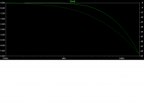
It looks like you sacrificed some stability to catch up to my speed. Your phase lag at 10 MHz is about 70 degrees, while mine, shown below, is only 43 degrees. Frankly, I don't think yours looks all that good in comparison. The one I'm showing below is the same circuit I used earlier, but with the 2SC3601/2SA1407 and 2SC5171/2SA1930 transistors in it.
One of the nice subtleties about the EC circuit is that the compensation provided by C1 and C2 rolls off the EC feedback while providing a feedforward effect to the forward path, minimizing bandwidth loss and excess phase introduction by the compensation.
Cheers,
Bob
Edmond Stuart said:
As for simulating a complete amplifier, why should I? Comparing the two output stages tells us anything we need to know. But I can assure you that my non-HEC OPS, combined with your front end will perform equally well and perhaps even slightly better.
(Actually I did that just that, by using Micro-Cap it's a snap 😀)
As for the frequency/phase response plot, why you ask me? You have all the tools and models to do it by yourself. Nevertheless, as I'm a really nice guy (sometimes), here they are. The 1st one with a 8 Ohm load and the 2nd one with a 4 Ohm load.
Cheers, Edmond.
Hi Edmond,
You may get some surprizes when you simulate the whole amplifier, that's all I'm saying.
It looks like I've either missed a post or two or you've changed your NFB version of the output stage again. If I'm reading your chart right, it looks like you have moved your 3 dB bandwidth out to about 8 MHz, and you are now actually at about +1 dB peak at 2 MHz. Ultimately, you appear to have about a 1.5 dB peak at about 3 MHz.
It looks like you sacrificed some stability to catch up to my speed. Your phase lag at 10 MHz is about 70 degrees, while mine, shown below, is only 43 degrees. Frankly, I don't think yours looks all that good in comparison. The one I'm showing below is the same circuit I used earlier, but with the 2SC3601/2SA1407 and 2SC5171/2SA1930 transistors in it.
One of the nice subtleties about the EC circuit is that the compensation provided by C1 and C2 rolls off the EC feedback while providing a feedforward effect to the forward path, minimizing bandwidth loss and excess phase introduction by the compensation.
Cheers,
Bob
Attachments
Re: Re: Re: Re: Re: Re: Re: Re: Re: Error Correction Sensitivity
And now we have a significant gap. My measurements under the same conditions (but at 4 ohm) show a much larger THD20 before EC (1.1% vs. 0.185%) and a much larger impact of the EC (120 vs. 45). Before any further sensitivity analysis, this gap has to be covered and explained. The vertical vs. lateral otput devices could cover part of this gap.
Bob Cordell said:
Performance of that very same simulation at 40V peak at 20 kHz into 8 ohms is as follows:
Without EC: THD-20 = 0.185 %
With EC: THD-20 = 0.0041 %
And now we have a significant gap. My measurements under the same conditions (but at 4 ohm) show a much larger THD20 before EC (1.1% vs. 0.185%) and a much larger impact of the EC (120 vs. 45). Before any further sensitivity analysis, this gap has to be covered and explained. The vertical vs. lateral otput devices could cover part of this gap.
Re: hec != hoax ?
Hi Edmond,
Thank you for commenting on my stature, but I don't always see the reasoning behind others' tricks. I guess I am a bit thick, and need more than just a hint. It is just not obvious to me.
So why don't you be an even nicer guy and just tell us precisely what your reasoning was in choosing the different gate stopper resistors and then the rest of us can comment on whether your reasoning makes sense.
Of course, if you used my gate zobels, you would not have to use such big-@ss gate stoppers in the first place 🙂.
Cheers,
Bob
Edmond Stuart said:
As for different gate stopper resistors, come on Bob, for a man of your stature, the answer should be quite obvious. I'll give you one hint: optical symmetry does not always coincidence with electrical symmetry.
Cheers, Edmond.
Hi Edmond,
Thank you for commenting on my stature, but I don't always see the reasoning behind others' tricks. I guess I am a bit thick, and need more than just a hint. It is just not obvious to me.
So why don't you be an even nicer guy and just tell us precisely what your reasoning was in choosing the different gate stopper resistors and then the rest of us can comment on whether your reasoning makes sense.
Of course, if you used my gate zobels, you would not have to use such big-@ss gate stoppers in the first place 🙂.
Cheers,
Bob
Re: Re: Re: Re: Re: Re: Re: Re: Re: Re: Error Correction Sensitivity
Yes, the 4-ohm condition (if you are using a single pair at 150 mA), combined with the poor performance of the laterals may largely explain it.
By the way, in my earlier 20 kHz simulation at 40 V pk, I showed 0.0044 % THD-20, but that was with the optimum 18 ohm trim resistor as determined by low frequency THD. So that experiment did not entirely answer your question about EC balance sensitivity at 20 kHz, 40 V peak.
That same simulation, run with the net EC resistance 1 % low, yielded 0.0055 %. So it is possible to say that a 1 % error in EC balance will allow the attainment of 55 ppm THD-20 in the EC output stage.
Cheers,
Bob
syn08 said:
And now we have a significant gap. My measurements under the same conditions (but at 4 ohm) show a much larger THD20 before EC (1.1% vs. 0.185%) and a much larger impact of the EC (120 vs. 45). Before any further sensitivity analysis, this gap has to be covered and explained. The vertical vs. lateral otput devices could cover part of this gap.
Yes, the 4-ohm condition (if you are using a single pair at 150 mA), combined with the poor performance of the laterals may largely explain it.
By the way, in my earlier 20 kHz simulation at 40 V pk, I showed 0.0044 % THD-20, but that was with the optimum 18 ohm trim resistor as determined by low frequency THD. So that experiment did not entirely answer your question about EC balance sensitivity at 20 kHz, 40 V peak.
That same simulation, run with the net EC resistance 1 % low, yielded 0.0055 %. So it is possible to say that a 1 % error in EC balance will allow the attainment of 55 ppm THD-20 in the EC output stage.
Cheers,
Bob
Re: Re: Re: Re: Re: Re: Re: Re: Re: Re: Re: Error Correction Sensitivity
Your own vertical MOSFET OPS measurements as revealed in your EC amp paper (150mA bias, 8 ohm) give the open loop THD “on the order of 1% as pictured in Fig. 10(a) and (b).”
Bob Cordell said:
Yes, the 4-ohm condition (if you are using a single pair at 150 mA), combined with the poor performance of the laterals may largely explain it.
Your own vertical MOSFET OPS measurements as revealed in your EC amp paper (150mA bias, 8 ohm) give the open loop THD “on the order of 1% as pictured in Fig. 10(a) and (b).”
That's right, Greg.
By my estimations Bob's 1984 OS, with EC disabled, produced a THD20 of about 1% or -40dB (-43dB H2, -55dB H3, -60dB H4) at 50W into 8-ohms resisitive with 150mA FET bias current.
Ovidiu, have you got the same figures for your OS under the same load and power conditions for comparison? I'm losing track of the numbers in all these posts but your THD20 seems to be in the same ballpark as Bob's.
In theory, if Bob were able to greatly reduce his even harmonics without increasing his odd harmonics he'd have a THD20 of -55dB or 0.18%. In his new simulation he appears to be measuring 0.185% at 100W into 8-ohms resistive...which would be consistent with his new simulation containing much less even order distortion.
Bob, can you say what the H2, H3, H4 sizes are without EC in your new simulation under the same power and loading as your 1984 measurements?
Brian
Re: Re: hec != hoax ?
Hi Bob
The rationale behind different gate stopper resistors is quite simple. We don't need equal resistor values, rather equal time constants.
Generally, the effective gate capacitance of a p-channel mosfet is about 2.3 times higher than its n-channel counterpart, that is, if they both have the same trans-conductance, on-resistance etc. Why this is, I don't know exactly, but, considering that the mobility of the majority carriers in a p-channel mosfet (i.e. holes) is two to three times lower, I guess that the size of the chip is much larger, hence larger capacitances. (Ovidiu, please correct me if I'm talking utter nonsense)
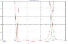
With equal gate stoppers we get unequal common mode currents at the positive respectively negative going zero crossing transitions. At low frequencies this is not much of a concern, but at 20kHz it may increase the cross-over distortion and in case of a square wave it may even lead to a dangerous cross conduction of the two output devices.
In the picture below, I've exaggerated this effect just for clarity by using an unrealistic high frequency, i.e. 100kHz.
Red curves: equal gate stoppers, 150 Ohm.
Green curves: unequal gate stoppers, 100 and 240 Ohm.
Regarding your 'gate Zobels', indeed, it is a very nice and valuable trick. I hope you don't mind if I borrow your method to tweak my NFB-OPS.
BTW, my preference also tends to small-@ss xxx in the first place. 🙂
Cheers, Edmond.
Bob Cordell said:Hi Edmond,
Thank you for commenting on my stature, but I don't always see the reasoning behind others' tricks. I guess I am a bit thick, and need more than just a hint. It is just not obvious to me.
So why don't you be an even nicer guy and just tell us precisely what your reasoning was in choosing the different gate stopper resistors and then the rest of us can comment on whether your reasoning makes sense.
Of course, if you used my gate zobels, you would not have to use such big-@ss gate stoppers in the first place 🙂.
Cheers,
Bob
Hi Bob
The rationale behind different gate stopper resistors is quite simple. We don't need equal resistor values, rather equal time constants.
Generally, the effective gate capacitance of a p-channel mosfet is about 2.3 times higher than its n-channel counterpart, that is, if they both have the same trans-conductance, on-resistance etc. Why this is, I don't know exactly, but, considering that the mobility of the majority carriers in a p-channel mosfet (i.e. holes) is two to three times lower, I guess that the size of the chip is much larger, hence larger capacitances. (Ovidiu, please correct me if I'm talking utter nonsense)
With equal gate stoppers we get unequal common mode currents at the positive respectively negative going zero crossing transitions. At low frequencies this is not much of a concern, but at 20kHz it may increase the cross-over distortion and in case of a square wave it may even lead to a dangerous cross conduction of the two output devices.
In the picture below, I've exaggerated this effect just for clarity by using an unrealistic high frequency, i.e. 100kHz.
Red curves: equal gate stoppers, 150 Ohm.
Green curves: unequal gate stoppers, 100 and 240 Ohm.
Regarding your 'gate Zobels', indeed, it is a very nice and valuable trick. I hope you don't mind if I borrow your method to tweak my NFB-OPS.
BTW, my preference also tends to small-@ss xxx in the first place. 🙂
Cheers, Edmond.
Attachments
Re: Re: hec != hoax ?
Hi Bob,
I can't find your schematic. Please, would you be so kind to drop it again, together with your latest mods?
Cheers, Edmond.
Bob Cordell said:Hi Edmond,
[snip]
The one I'm showing below is the same circuit I used earlier, but with the 2SC3601/2SA1407 and 2SC5171/2SA1930 transistors in it.
[snip
Cheers,
Bob [/B]
Hi Bob,
I can't find your schematic. Please, would you be so kind to drop it again, together with your latest mods?
Cheers, Edmond.
- Home
- Amplifiers
- Solid State
- Bob Cordell Interview: Error Correction