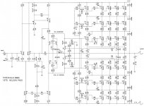
Hav'nt seen this kind of "mosfet" (hex i my case irfp somethng) stage anywhere..
http://dsl.mine.nu/out.gif
Is it because it's cräp or did I not search enough or did I do a useful thing for a change?..
I'm using it and I'm pleased with the sound hmm there's a bunch of theories that made me connect them in that way a while ago.. something with current and linearity in the component.. hmm or I might have misunderstood the datasheet hmm
nikwal said:Hav'nt seen this kind of "mosfet" (hex i my case irfp somethng) stage anywhere..
http://dsl.mine.nu/out.gif
Is it because it's cräp or did I not search enough or did I do a useful thing for a change?..
I'm using it and I'm pleased with the sound hmm there's a bunch of theories that made me connect them in that way a while ago.. something with current and linearity in the component.. hmm or I might have misunderstood the datasheet hmm
Hi,
that looks like a cascode that swings with output voltage.
It reduces the voltage across any device by about 50% compared to the non-cascoded version.
See Leach super amp or Nelson's own circuit for BJT versions.
AndrewT said:Hi,
that looks like a cascode that swings with output voltage.
It reduces the voltage across any device by about 50% compared to the non-cascoded version.
It is called usually "totem pole" and was used before, especially when higher voltage transistors were not available. My Creek 5350 design (and A52 before that) also used a similar configuration in the output stage, thought it was N-channel only. It is an alternative to paralleling devices to dissipate more power and I found it is better than a parallel connection for MOSFETs as it keeps only one pair of devices in control of the output.
Cheers
Alex
x-pro said:
It is an alternative to paralleling devices to dissipate more power and I found it is better than a parallel connection for MOSFETs as it keeps only one pair of devices in control of the output.
Cheers
Alex
Alex,
This kind of arrangement is also used in Class-G amps, in that case SOA safety is much more extended also......🙂
Workhorse said:This kind of arrangement is also used in Class-G amps, in that case SOA safety is much more extended also......🙂
Class G makes use of switching between different rail voltages and that makes it much more efficient. Here we deal with a usual class AB and a dual rail arrangement.
Cheers
Alex
nikwal said:Hav'nt seen this kind of "mosfet" (hex i my case irfp somethng) stage anywhere..
http://dsl.mine.nu/out.gif
Is it because it's cräp or did I not search enough or did I do a useful thing for a change?..
I'm using it and I'm pleased with the sound hmm there's a bunch of theories that made me connect them in that way a while ago.. something with current and linearity in the component.. hmm or I might have misunderstood the datasheet hmm
I haven't seen this with MOSFETs either, but it is a useful configuration, as others here have mentioned. I believe that Bryston still uses it to this day in their hi-powered amps. It originated in earlier times when SOA of output transistors was not as good as it is today. By halving the voltage across the output transistors, it helps SOA a lot. It also has a partial cascode benefit AND it also has a partial benefit of shielding the inner output transistors (that really do the audio work) from garbage on the power supply rails by a factor of about two.
Cheers,
Bob
Bob Cordell said:It originated in earlier times when SOA of output transistors was not as good as it is today.
It has been used with some enthusiasm:
www.passlabs.com/np/800a_schem.tif
😎
Attachments
Bob Cordell said:
I haven't seen this with MOSFETs either, but it is a useful configuration, as others here have mentioned. I believe that Bryston still uses it to this day in their hi-powered amps. It originated in earlier times when SOA of output transistors was not as good as it is today. By halving the voltage across the output transistors, it helps SOA a lot. It also has a partial cascode benefit AND it also has a partial benefit of shielding the inner output transistors (that really do the audio work) from garbage on the power supply rails by a factor of about two.
Cheers,
Bob
Bob
Bryston use something different which is a combination of emitter
follower and CFP in the same OP stage. Their config is quite unique.
I'm thinking the cascoded OP stage isn't very popular probably due
to the fact that it really eats into headroom which is precious in the
OP stage.
cheers
Terry
If the supply voltage is that high then the loss of an extra couple of volts is hardly noticed.Terry Demol said:
I'm thinking the cascoded OP stage isn't very popular probably due to the fact that it really eats into headroom which is precious in the OP stage.
Compare that to the same two transistors in parallel operating from half the supply voltage. The losses here will be higher and the result will be less overhead.
Terry Demol said:
Bob
Bryston use something different which is a combination of emitter
follower and CFP in the same OP stage. Their config is quite unique.
I'm thinking the cascoded OP stage isn't very popular probably due
to the fact that it really eats into headroom which is precious in the
OP stage.
cheers
Terry
Hi Terry,
Yes and no. In their lower power amplifiers they use a single level of output transistors, but they are arranged in a rather unique composite emitter-follower/CFP configuration. However, when they go to their higher power amplifiers, they insert another layer of output transistors in series. That's what I was referring to. You are right in that what is in those layers is not just a simple emitter follower structure.
Cheers,
Bob
Bob Cordell said:
Hi Terry,
Yes and no. In their lower power amplifiers they use a single level of output transistors, but they are arranged in a rather unique composite emitter-follower/CFP configuration. However, when they go to their higher power amplifiers, they insert another layer of output transistors in series. That's what I was referring to. You are right in that what is in those layers is not just a simple emitter follower structure.
Cheers,
Bob
Thanks Bob,
Very interesting, I haven't seen these other designs.
So they still use the CFP+EF but insert a cascoded ollower 'above'
this whole OP structure.
To me it does seem like added complexity for relatively small gain.
I would think that the current modulation due to OP load causes
way more non linearity than voltage modulation across OP
devices.
One thing it would do is give much higher PSRR for OP stage
(sans FB), maybe that is a design motivation.
cheers
Terry
Interesting discussion of the Bryston output stage here:
http://www.bryston.ca/BrystonSite05/pdfs/MiscDocuments/OUTPUT-STAGES.pdf
http://www.bryston.ca/BrystonSite05/pdfs/MiscDocuments/OUTPUT-STAGES.pdf
Hi Jim,
That document is about as much advertising as it is factual.
One thing I disagree with strongly is the "matched output transistor" nonsense. Having serviced a few of these, I can tell you that the outputs are matched only in part number. The devil seems to be in the details. Details they are not giving the reader.
-Chris
That document is about as much advertising as it is factual.
One thing I disagree with strongly is the "matched output transistor" nonsense. Having serviced a few of these, I can tell you that the outputs are matched only in part number.
The devil seems to be in the details. Details they are not giving the reader.-Chris
Bob Cordell said:they are arranged in a rather unique composite emitter-follower/CFP configuration.Cheers,
Bob
This composite configuration lets all the Brystons to cross-conduct heavily when subjected to frequencies above 10Khz.........
Workhorse said:This composite configuration lets all the Brystons to cross-conduct heavily when subjected to frequencies above 10Khz.........
Is that a feature?
😎
Workhorse said:
This composite configuration lets all the Brystons to cross-conduct heavily when subjected to frequencies above 10Khz.........
Kanwar
WRT the amp mentioned, which OP devices x conduct, the followers,
the common emitter devices, or both?
BTW, I haven't had time to analyse this OP stage closely.
cheers
Terry
Kanwar is quite right, though we found problems slightly higher - like 20kHz - 30kHz and more.
Terry Demol said:
Kanwar
WRT the amp mentioned, which OP devices x conduct, the followers,
the common emitter devices, or both?
BTW, I haven't had time to analyse this OP stage closely.
cheers
Terry
Normally CFP is more prone to cross-conduction. The reason is that they are only the resistors to drain charge from the B-E junction of 2nd device.
No, its a flawed featureNelson Pass said:Is that a feature?
😎
Terry Demol said:
Kanwar
WRT the amp mentioned, which OP devices x conduct, the followers,the common emitter devices, or both?
cheers
Terry
CE devices!!
I once tested 7B SST which was showing cross-conduction at open circuit current in excess of 5 amperes at 10KHZPMA said:Kanwar is quite right, though we found problems slightly higher - like 20kHz - 30kHz and more.
- Home
- Amplifiers
- Solid State
- Bob Cordell Interview: BJT vs. MOSFET