HarryHaller
I shouldn't have to chase you around to get a simple answer to a question. Since when does enlightened mean stingy with information. I need to know which is correct if any:
(a)The Aleph-X source resistors power dissipation is 0.5V times the bias current through its mosfet.
(b)The Aleph-X source resistors power dissipation is the same as its mosfet.
(c)The Aleph-X source resistors power dissipation is the current through its mosfet squared times the source resistor value.
Since you guys are into short answers, I decided to make it easier for you.
Resistor power dissapation
A. Yes if there is 0.5 volts source across resistor. Power = Voltage times current.
B. No
C.Absolutely
See You really did not need my help at all.
H.H.
http://links.epanorama.net/links/basics.html
A. Yes if there is 0.5 volts source across resistor. Power = Voltage times current.
B. No
C.Absolutely
See You really did not need my help at all.
H.H.
http://links.epanorama.net/links/basics.html
Peter Daniel
Thanks. Now, what determines the maximum Voltage drop on these source resistors assuming an Aleph-X with +/- 25.6V rails?
Thanks. Now, what determines the maximum Voltage drop on these source resistors assuming an Aleph-X with +/- 25.6V rails?
HarryHaller
I missed your reply, so don't think it was a snub to only thank Peter Daniel. So the current through the source resistor is equal to that which runs through its accompanying mosfet regardless of the power supply rails?
ex: 25.6V rails 0.5ohm source resistor and 1A through each mosfet. The source resistor in this case can be as low as 2W rated and do the job?
Under the  of HH…
My ignorance shining…
Shining in the sky…
Towards the public…
Among others…
LED voltage drop…
That is non-zero…
That is to be greater than zero…
 ...
...
 ...
...
...
...
JH
of HH…My ignorance shining…
Shining in the sky…
Towards the public…
Among others…
LED voltage drop…
That is non-zero…
That is to be greater than zero…
... ... ... ...JH
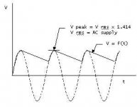
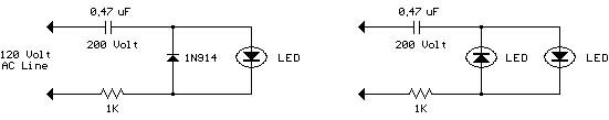
Reference: My attachment above.
At the joint between IN4004 and the resistor, I made a rough voltage-time curve. The voltage is prior to a consideration of the barrier voltage of about 0.66 in IN4004 and the LED voltage drop.
Now, I am ready to estimate the reliable size of the resistor based on the LED current. And, I could also estimate the time average power.
HH
--------------------------------------------------------------------
Does anybody know how to do this with a green LED?
--------------------------------------------------------------------
Maybe I simply paint it with my blue oil pen.
JH
Attachments
The blue LEDs I've been using on my Aleph 2's are now down to
0.25 mA of current.
You connect the LED forward biased between the positive rail and the circuit ground. Don't worry about "electrical balancing" as
it is a minor effect and you'll never know any difference.
A LED if I'm not mistaken will conduct at a forward biased voltage of about 0.7V or so but it may be slightly higher. It is certainly not more than 2V.
Resistance = (voltage / current) to calculate the resistance you need. Just use the rail voltage of your amp and 0.00025 for the current and the resistance will be given in ohms.
Put the resistor between the positive rail and the LED's anode, and connect the LED's cathode to ground.
Forward biased means that the arrow on the LED symbol points from positive rail to ground on a schematic.
THe longer lead on the actual LED is the anode and is the lead that goes to the resistor which is connected to the positive rail of your supply.
OK, it's terse but I don't have a lot o time right now and I think I covered all your questions.... good luck.
Oh, another quick thing or two...
the LEDS I used are Digikey P467-ND. THey're beauuuutiful.
I started out at 2 mA of current and I think I spot-welded part of my retinas from across the room at this current level. You definitely want the current to be low..... As I said I'm at 0.25 mA
now and that's about where I'm going to leave them I think.
W.
Beautiful Blue LED's.
I have recently been doing some experiments with these LED's and agree that they do have a distinctive color. Wayne, if you think that your LED was bright you should try the other two variations of the LED that you have (P466 and P465.) They are both brighter by 2 and 4 times, respectively.
During the experiment these blue LED's showed a forward voltage drop of 3.0 V to 3.75 V with currents ranging from a couple of mA to 30 mA. The P466 was unbelievably bright at 30 mA--blindingly bright if directly infront. With optics they can transmit quite some distance.
On the DIY front, I was planning on using them to back light the heatsinks on one of my projects for a "Heavy Metal" type of effect.
Later,
Blue LED light goes off quick or slow
Quick questions ....
When you guys turn off the Aleph 2 amps that uses the blue LED (P457-ND), does the light goes off gradually over a period of a few minutes or a few seconds?
And what is the reason behind why the LED lights go off slowly or quickly?
Quick questions ....
When you guys turn off the Aleph 2 amps that uses the blue LED (P457-ND), does the light goes off gradually over a period of a few minutes or a few seconds?
And what is the reason behind why the LED lights go off slowly or quickly?
Depending on how you wire the amp and the LED it may go off immediately or fade out over a period of a few seconds or so. Usually when you turn off the amp, the power supply caps must discharge so the rails can go low. During this time, the LED will fade out. With a little additional circuitry, you can disconnect the rails immediately when power is cut. In this case, the LED goes out immediately.
They may look cool but how do they sound?
LEDs add distortion that is audible. When I had an Aleph 3 the first thing I did was to remove the blue LED. It was wired from the positive supply to the output of one channel. Much better sound with it removed.
After you have put in an LED and listen for awhile, try removing it. Unless the LED is very isolated from the circuit on its own power supply and transformer, it should audibly mess up the sound. It makes the sound more grainy and two dimensional. More air and space and purity with them gone.
If you cannot hear it then fine. I personally have removed them on several amps, players, etc. always with good results.
Less is usually better!
Ric Schultz
fcel
My understanding goes this way. After the power is switched off,
the main capacitors discharge themselves, partly through the LED of
small ampere eater. This is why the LED light fades off that slowly.
The bigger the main caps, the slower fading off.
For me, I use the little additional circuitry as indicated by AudioFreak.
You could find my circuitry in this thread. It works fine.
The light turns off immediately. I'm not kidding.
JH
Heck! I didn't read AudioFreak's writing carefully.
fcel, his explanation is better.
Hmmmm... on the sound being better with the LEDs gone, I'm skeptical. But I'm open minded enough to remove it and see if I can hear any difference or not. Looks like a speriment to try this wknd... Since the cathode is connected to the signal ground, could it be that the recombination of the minority carriers is electrically noisy enough for it to affect the sound of the amp ? Maybe using R/2 between the cathode and ground, and R/2 between the supply and the anode will clean up the sound again ? Then the diode is isolated from the ground.... Or,
maybe connecting the anode to power through the limiting R and connecting the cathode to the chassis ground (isolated from signal ground by a thermistor) will work good... ideas to try.
I think you could use these blue LEDs at 30 mA to cut metal....
About the LEDs going out over time... since the caps in the power supply take time to discharge, the LED will be on for a few seconds. In my power amps with huge caps - 44000 uF per rail - the lights go out after the 3/4 second it takes to discharge. Then as the caps begin to generate a forward voltage again after the initial dscharge, the LEDs go back on at a low intensity and stay that way until the caps bleed down to 0 through some 100k resistors I added for that purpose. THis takes several minutes - like 10 or 20....
W.
Hey guys, I don't mean to drag this little LED issue to death but it has been bothering me lately. I want to get some feedback (thank you guys) before I tear my Aleph 2 amp (1 channel) apart.
I have 52,000uf per rail with 200K in series with the blue LED that is connected to the positive rail. On one channel, the LED light would go completely off in about 15 minutes like what Wayne says. But the other channel, it goes off in about 1 or 2 minutes. Both channel are constructed in exactly the same manner and 1 LED light goes off so quick that it bothers me. I would think that the LED light that goes off in about 15 minutes because of capacitor discharging is pretty normal but the other channel ... May be it's a partially defective LED? Possible?
I have 52,000uf per rail with 200K in series with the blue LED that is connected to the positive rail. On one channel, the LED light would go completely off in about 15 minutes like what Wayne says. But the other channel, it goes off in about 1 or 2 minutes. Both channel are constructed in exactly the same manner and 1 LED light goes off so quick that it bothers me. I would think that the LED light that goes off in about 15 minutes because of capacitor discharging is pretty normal but the other channel ... May be it's a partially defective LED? Possible?
One explanation would be that these are not exactly same LEDs and one draws more current than the other. The best way to check it out would be switching them. If they produce the same amount of light you shouldn't be worried.🙂
Yeah, they pretty much put out the same amount of light that I can see but it's this whole thing about Pass amp being "balancED", "monoblockED", "symmetricallED", "matchED" that drives me to get the LED light to go offED at the same time.
Well ... I will change out the LED on one of the weekends to see how it goes.
Well ... I will change out the LED on one of the weekends to see how it goes.
If it's not too much trouble, I'd be thinking that the caps are defective and you might want to check them out. Just turn the amp on for a few seconds - maybe 10, then turn it off and draw a voltage vs time graph for the + rail for say every minute until it is discharged. Do this to the amp where the light is going out quickly. If it turns out that the LED is going out when there is significat rail voltage (these caps will go back up to about 7V or so after the initial discharge...) then replace the LED. If the caps in one amp behave much differently than the ones in the other, then I'd be pointing the finger at the caps (more than likely it will be only 1 of the pair if you have 2 paralleled) and then go the extra trouble of testing those after removing from the amps.
W.
W.
- Status
- Not open for further replies.
- Home
- Amplifiers
- Pass Labs
- Blue LED for BOSOZ, how to implement?