I just finished my s-5 k-16LS kit and plugged it in for my first ever tube experience. There was a loud pop and a bright light and that's it. I'm hoping someone can help me figure out what went wrong.
The resistor that blew up was a bleeder resistor on the first power cap. I installed 270K resistors across the leads of each electrolytic cap according to the safety page on bottlehead. The power rating was 1W. I also upped the capacitance of the second and third power caps, but not the first (on which the bleeder blew). The capacitor still looks as though nothing bad happened to it. Another thing I was suspicious about is a cooling fan that is connected to wall power before the primary. Its specs are 115VAC, 130mA, 10W max. The 1 1/2 amp fuse before the PT primary is still fine.
I would just remove the bleeders and give it another shot, but I really don't want to blow up a cap or do any more damage. Any advice?
Can you post a schemo of the power supply? It takes over 500Vdc to poof a 270K / 1W resistor. Are you sure it didn't just flash-over? That's a lot of voltage across one resistor.
Definitely don't remove the bleeders, and don't try again until this problem is sorted out.
Definitely don't remove the bleeders, and don't try again until this problem is sorted out.
Is there any chance that the resistor that failed could have accidentally been something other than 270k ohms, perhaps 27K? I've done that before when the colour bands on different resistances were too similar to differentiate without actually measuring the resistance.
Just a thought from my own experience.
Just a thought from my own experience.
Can you post a schemo of the power supply? It takes over 500Vdc to poof a 270K / 1W resistor. Are you sure it didn't just flash-over? That's a lot of voltage across one resistor.
Most commonly available resistors have a max working voltage rating of 350V. I know that means it's not really a 1W. It's a conspiracy with part manufactures I tell you. It is doubtful that kit uses more than 350V though.
Double check the values are right and that everything is stuffed in the right place. Also, make sure the caps are connected in proper polarity. Trace the traces to verify so. The S-5 kit I bought (was a k-502) had the silk screen backwards which caused me to blow the power supply caps.
Here is the schematic. The resistors are indeed 270K 1W. C7 on the PCB is located right in line with C10 and C11, so I took it to be one of the power caps as well -- I put bleeders on all the electrolytics. The capacitors were in the correct polarity as well.
Attachments
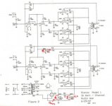
Sorry that image is such poor quality. I had to reduce my scan way down for the site to let me post it.
Run it without the one that blew. All the caps will still discharge without it as long as you leave the other bleeders. It just may take a little more time to discharge the one without.
I agree with Jeb. You already have a bleeder on the next cap and it will take care of discharging all of the capacitors. If the amp appears to work fine otherwise, run it that way.
Now it's R26 (between the two 220uf electrolytics) and the bleeder on c11 that are going out. They are just getting dark and smoking as opposed to flaming instantly.
- Those caps that you increased in value, is the voltage rating at least the same as the originals?
-Make sure those electrolytics aren't in backwards.
-Try leaving the C7 bleeder only.
-What is the voltage rating on C7? That should give an idea of operating voltage for the circuit. Make sure the Max working voltage of the resistors your using for the bleeder are at least that value.
-After the brief power up with C7 bleeder only. Quickly feel the insulated part of the caps to see if their heating up. Only use one hand and be careful not to touch anything else, as the circuit may not be completely discharged by this time.
-Remember not to apply a signal without a load attached.
fenpark15 said:Now it's R26 (between the two 220uf electrolytics) and the bleeder on c11 that are going out. They are just getting dark and smoking as opposed to flaming instantly.
That indicates there is a significant amount of current draw in the B+ circuit.
The S5 webpage indicates that the kit can be operated in 120/240 volts. Is the power transformer wired correctly?
Then, measure the B+ as soon as power is applied. Is the voltage within spec or is it loaded down, indicating a possible short? Next, take out the output tubes and measure B+ again. Does R26 start to smoke in this case?
-- josé k.
hoho, let's not make this anymore confusing as it is. bleeder resistors don't burn out if there is a short in the circuit elsewhere.
keep it simple, think about Mr. ohm.
First bleeder resistor:
A) Resistor value was too low
B) Voltage across resisitor was too high
Topicstarter claims resistance is the right 270000 ohms, so voltage must be really high. No other way that it would fry that way.
Now the first bleeder is away, so the next will go. That it takes the resistor between the caps too seems like no surprise then!
I'd disconnect everything and measure secondary AC first.
Having said that, i think that fenpark should check the resitors AGAIN
Why?
Well, if i look at the schem, the resistor between the caps is rated 470 ohms. If BOTH the bleeder and the series resistor get hot, and i suppose they are within eachothers range in power dissipation, there is no way that the beleeder is indeed 270000 ohms.
If the bleeder was 270000 ohms and power was rated at 1 watt, it would only burn up like that with some 5-20 watts or more. that means that P = V^2 * R, there need to be some odd 1000 - 2000 volts to blow it up....
I'd be supercareful in measuring your output voltage if thet resistor really is the right resistance, but i seriously doubt it...
Please desolder and measure the resistors, don't rely on color codes or what the guy who sold them to you said they were.
When i ask for 470k resistors in the store, I regularly unpack 470 ohm resisitors at home. They are human too.
If it really are 270 ohm resistors, things would be easily explained. The first blew violently as there was about 1 amp @ 250 volts running through it, translating in 250 watts. That blows up resisitors.
The next is series with 470 ohm, so would be 780 ohm total, translating in about 50 watts dissipated in the 470 ohm resistor, rated at 5 Watt. That should give a rapid browning.
Thanks for all these suggestions. I'm out of town for a couple of days and will check on all of that stuff when I get back. I hope to get it sorted out soon!
fenpark15 said:Sorry that image is such poor quality. I had to reduce my scan way down for the site to let me post it.
Save black and white images as GIF files, not JPG. They'll be much easier to read that way.
Good luck trying to run down the cause of the trouble. For what it's worth, I'm betting on the bleeder resistors being the wrong value.
Thanks for fixing the schematic. I tested the resistors with a meter and they are 270 Ohm instead of 270K. Parts Express sent me these in a bag labeled 270K.
That explains why the bleeder resistors are going out. But does that also account for the 470 ohm R26? It started smoking after I removed the first bleeder on C10. Should changing my bleeders to true 270Ks potentially solve this?
Also, the R26 I have on the PCB is darkened now. It still tests its correct value with a meter. Will this work or should it be replaced?
Yes R26's power rating would be exceeded due to the circuit drawing to much current because of the undervalued bleeders on the other caps. It's advisable to change R26, but if it meters good it probably isn't absolutely necessary.
As I pointed out earlier: yes, that accounts for r26 too
You are well adviced to exchange it.
Bas
edit:
I see JEB-D was quicker to reply.
Fenpark, please learn to use the most elementary equasions in electronics.
You will find people being more helpfull when you encounter bigger problems if you show you can tackle small problems.
I am in no way trying to tell you off, but the calculations i made in my earlier posts should have given you the answers right away.
- Status
- Not open for further replies.
- Home
- Amplifiers
- Tubes / Valves
- Blown up resistor in S-5 amp kit...