no, didn't have more than .001 on any channel, Yes the relay clicks in. Now that I have this thing mounted up, It is starting to blow the inline fuse. And makes a hissing sound out of the mosfet area. It won't let me keep it on long enough to determine exactly where it is from. Also the c15a gets really hot real quick. It gives me about 10 secs. before it blows the fuse.
Perry, I am sure mine never had those washers on it. We do mercedes, bmw dash work and are very very careful when we take things apart. Mine has two plastic spacers installed that make sure the screw never touches bottom. I have installed the washers and it quit hissing and blowing fuses.
Amp 1 works all channels. Amp 2 dead. The sub channel works but we have a low voltage and it didn't seem to have enough to keep the speaker moving. I was testing with a woofer. Didn't have anything smaller on hand to try with.
For amp 2, did you try the switches in all positions and the correct set of RCA jacks?
http://www.kicker.com/sites/default/files/2008 ZX 550-3 700-5 c01 web.pdf
http://www.kicker.com/sites/default/files/2008 ZX 550-3 700-5 c01 web.pdf
we are using an ipod and had to disconnect from amp 1 and connect to amp 1 to try amp 2. Yes I tried in all positions.
Are the gains at the max position?
Short the shields of amp 1 to amp 2 while driving signal into amp 2. Does amp 2 produce output?
Short the shields of amp 1 to amp 2 while driving signal into amp 2. Does amp 2 produce output?
no gains aren't in max, but tried moving up and down. But, this time we turned it on and amp 2 worked. Doesn't sound exactly like it should, not alot of bass but it worked. We let it run for about 20 min and it worked the whole time no smoke or anything..
That !@#$%^& ipod is likely the cause. Try it with a standard head unit that's grounded to the same power supply as the amp. If the crossover is off, it should work properly (although I've seen kicker amps do some strange things on the second 2 channels when there was no shield ground connection to the first two channels).
The problem with the sub channel may be the same as it was for amp 2. Again, try it with a standard head unit.
If you don't have a standard head unit, short the shields of the sub channel to those of amp 1.
The problem with the sub channel may be the same as it was for amp 2. Again, try it with a standard head unit.
If you don't have a standard head unit, short the shields of the sub channel to those of amp 1.
jajajaja, guess you were right again. We have it sitting in my car hooked up with all things that I have fixed and running. So far everything is working. I'll let it run for a couple of hours and see if it shoots flames out....
Now that you see that all channels are working properly, you need to solder Q04 back into the circuit. If it goes into protect, we'll have to try to troubleshoot the protection circuit.
Don't play it for too long with the protection circuit disabled. If something fails, it could cause extensive damage.
Don't play it for too long with the protection circuit disabled. If something fails, it could cause extensive damage.
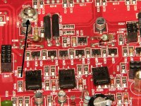
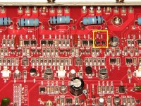
Lift the two transistors highlighted in the attached photo. Does it still go into protect mode?
When you lift them, apply enough solder to bridge the two adjacent legs so you can heat both at the same time. Apply heat and lift the transistor to a 30-45° angle. Remove the solder from those two legs and leave the transistor in place (see attached).
Make a note of the markings on the transistors before you try to desolder them.
Attachments

erase that last message, I just noticed solder between the pads and got rid of it and gave the amp power and it powers up now.
- Status
- Not open for further replies.
- Home
- General Interest
- Car Audio
- blown two zx 700.5s and two deq 9200a