Very low indeed and beryllium version should be slightly better still. I would love to use them to build a clone of KH420/S5V style monitors, but the double waveguide is going to be hard stuff to tackle. I'm also thinking on expanding this concept into 4 ways, fully active of course, go full crazy why not, like using 15" ellipticor for example.
Here are some waveguide specialists and superheros active - maybe someone is interested in such a design? Would be GREAT for the DIY community!
As far as I remember are the designs of these 3" waveguides pretty simple - linear with radius or just radius. The transition between the speakers would be interesting to get right.
Full range loudspeaker systems are always 4 way in my designs - but the lowest way is a woofer system setuped and measured especially for the room. I try to install at least a singel bass array. Then it's possible to get precise low frequencies down to 20Hz.
You are right it does not seem to need to be particularly complicated, conical sections and radiuses work well.Would be GREAT for the DIY community!
As far as I remember are the designs of these 3" waveguides pretty simple - linear with radius or just radius. The transition between the speakers would be interesting to get right.
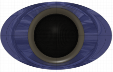
An elliptical version with quite a steep vertical wall angle simulates surprisingly well (with the included waveguide lip on the driver) terminating into an infinite baffle.
Attachments

Looks great! How deep is this shape? Could you leave the protection grid on when you start 2mm wider?
For a speaker that big and loud where I would use a 3" mid dome - I would love to get a wider waveguide to start focusing at lower frequencies. Maybe not as big as KH420 but at least to match an 8" driver.
https://de-de.neumann.com/kh-420#technical-data
(btw - did you simulate the AL or silk version?)
Hi,
I'm curious what function so small waveguide has? Is it to recess the driver to keep it safe while moving the speaker around or some other practical thing? If I compare to datasheet responses there doesn't seem to be much change in directivity.
I'm curious what function so small waveguide has? Is it to recess the driver to keep it safe while moving the speaker around or some other practical thing? If I compare to datasheet responses there doesn't seem to be much change in directivity.
I would have to check but I think about 18mm up from the existing lip. The waveguide starts exactly where the protection grid finishes on purpose as I do not want to have to take it off, as there is more risk of misaligning the magnet system in the Mid.Looks great! How deep is this shape? Could you leave the protection grid on when you start 2mm wider?
The width can be whatever is chosen, this was a test example to see if the result would be bad having such a steep vertical angle and it was surprisingly good.For a speaker that big and loud where I would use a 3" mid dome - I would love to get a wider waveguide to start focusing at lower frequencies. Maybe not as big as KH420 but at least to match an 8" driver.
https://de-de.neumann.com/kh-420#technical-data
The profile is the same as a circular one I made just swept around an ellipse instead of a circle.
This is for the Silk and Paper as they have the same dome profile.(btw - did you simulate the AL or silk version?)
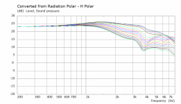
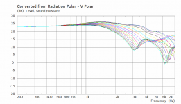
It gives a little more directivity in the Horizontal and quite a bit more in the vertical. It is different to the bare driver simulated in an Infinite baffle.Hi,
I'm curious what function so small waveguide has? Is it to recess the driver to keep it safe while moving the speaker around or some other practical thing? If I compare to datasheet responses there doesn't seem to be much change in directivity.
These are 5 degrees 0 - 90 degrees except the observation spectra doesn't quite make it to 90@fluid - what is the angular divisions on your simulation plot? are there 10 degrees per division?
Nice - could be just back wall mounted and routed in the baffle.I would have to check but I think about 18mm up from the existing lip. The waveguide starts exactly where the protection grid finishes on purpose as I do not want to have to take it off, as there is more risk of misaligning the magnet system in the Mid.
I also was surprised but there seem to be a 0 at already about 3k vertically - that's the price to pay.The width can be whatever is chosen, this was a test example to see if the result would be bad having such a steep vertical angle and it was surprisingly good.
The profile is the same as a circular one I made just swept around an ellipse instead of a circle.
After all good to know this is probably mores simple as we thought.
(btw - don't unscrew the 3"! I got a big warning from Bliesma about that 🙂. But you can remive the grids relatively easy with soome force and a small tool to get into the wholes, but not the membrane 😉 )
I checked and it's 22.3 mm from the top of the drivers waveguide lip to the baffle termination point, so with 25mm material it could be routed out of the baffle in one sheet.Nice - could be just back wall mounted and routed in the baffle.
Also to show the scale in case it seems small the width is actually 200mm
For a 3K crossover point it's no problem but if someone wanted to cross higher it could be adjusted. Increasing vertical directivity is quite useful if the ceiling isn't going to be treated.I also was surprised but there seem to be a 0 at already about 3k vertically - that's the price to pay.
If the grid and waveguide lip is removed then a more drastic profile could be used, my aim was to see what could be done leaving them on.(btw - don't unscrew the 3"! I got a big warning from Bliesma about that 🙂. But you can remive the grids relatively easy with soome force and a small tool to get into the wholes, but not the membrane 😉 )
Here is a normalized Horizontal graph that can be directly compared against Hificompass's normalized plots, the paper version is probably the best one to use as hard diaphragms tend to be more like a simulation.
I'm curious what function so small waveguide has? Is it to recess the driver to keep it safe while moving the speaker around or some other practical thing? If I compare to datasheet responses there doesn't seem to be much change in directivity.
I thought the same thing, until @fluid clarified that the lines on his plot in post#103 were 5 degree divisions. In truth, the IB mounting of the M74B gives us a 60 degree horizontal response of -2 dB at 2k, and -5 dB at 3k (according to hificompass)... The waveguide gives us -6 dB at 2k, and -8 dB at 3k. This is a substantial increase in directivity.
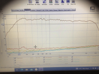
bliesma m74 b-6 in 45 cm Stereolab horn
Attachments

Looks good! The horn mouth doesn't fit the driver diameter? Is there a low pass filter installed?
Yes 48db 4000 hz and 24 db 400 hz
the driver is loosely positioned in the horn
i don't want to cut the horn,
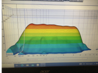
this was only a test, whether this driver can possibly fit in a horn/large waveguide, depth approx. 19 cm on the target image above
A properly fitted neck, this dom will play to about 6k in this horn.I think
the driver is loosely positioned in the horn
i don't want to cut the horn,
this was only a test, whether this driver can possibly fit in a horn/large waveguide, depth approx. 19 cm on the target image above
A properly fitted neck, this dom will play to about 6k in this horn.I think
Last edited:
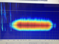
The resolution of your SPL curve is pretty high, so it is most likely not anechoic. Can you gate the echoes and show the anechoic SPL curve? Or share the raw impulse response data?bliesma m74 b-6 in 45 cm Stereolab horn
Suppose you mean pretty low? (and in 10 dB/div scale)The resolution of your SPL curve is pretty high,
II am referring to the frequency resolution. Gating for anechoic data will result in a frequency resolution of about 300 Hz or so. This means the curve would have data points at 300 Hz, 600 Hz, 900 Hz, 1200 Hz, etc.
Can you share thd raw impulse response data?
Can you share thd raw impulse response data?
Resolution of 300Hz ... I would say that's guessing, not measureing. You need a higher room my friend 🤓.
Na, looks only partially good to me. Approx. 0.7% HD above 1kHz is much above the THD level than what hificompass.com measured "as is", and really not so impressive. Furthermore, a well-matched, well-made and well-fitted horn would be expected to lower the THD figures altogether.Looks good! ...
So, what is going wrong here? Is this specific driver (e.g. the DIYAUDIO-measured DUT) flawed? Or one of these measurements (method/mic)? Or may this high THD figure result from the driver-to-horn-mismatch resulting from the described (simplyfied / horn-sparing) setup? Or whatelse?
Trosse1 did not state the input voltage of this measurement. Coincidally, this seems not so imporant, because the measurements of hificompass all show more or less similar results for freq. >1kHz at very different input levels. Instead, below 1kHz there are huge differences. Anyway, it would have been appreciated to know about the setup conditions of this measurement here.
Last edited:
- Home
- Loudspeakers
- Multi-Way
- Bliesma M74 series 3” dome midrange lineup