If you will mount new ICs please use a metal U-bracket per IC to evenly divide mechanical force. It helps a lot.
It is unlikely that you will get fake/chinese TA7270P ICs due to age and totally uninteresting features for people that counterfeit ICs.
TDA7394 and many of the others in that range can be nice replacements.
It is unlikely that you will get fake/chinese TA7270P ICs due to age and totally uninteresting features for people that counterfeit ICs.
TDA7394 and many of the others in that range can be nice replacements.

Yep, I'm aware that power is limited by voltage (if step up is not the case), but from my experience one radio will sound like **** and other will sound better / handle the power better, both without any step up, both with same power rating.Mmmmm. More power: No. Power = (battery voltage)^2 / load impedance.
It doesn't depend upon IC part number.
In any case the IC MUST support the current with minimum lost.
I have no theory to back up what I just wrote, it is just what I hear that is coming from the speakers. Seems to be the quality of the ic.
Yep, you hit the point there. I agree.If you will mount new ICs please use a metal U-bracket per IC to evenly divide mechanical force. It helps a lot.
It is unlikely that you will get fake/chinese TA7270P ICs due to age and totally uninteresting features for people that counterfeit ICs.
TDA7394 and many of the others in that range can be nice replacements.
Yes some old IC amplifiers sound like garbage and some can be HiFi like. Now a shocking revelation: some of a selected group of IC class AB amplifiers are liked better when compared with modern very high power complex car amplifiers.
Anyway TDA7394, 7388 etc can be implemented with a minimum of extra parts and on a small PCB.
Anyway TDA7394, 7388 etc can be implemented with a minimum of extra parts and on a small PCB.
Not the subject I think. Some just like music in the car as the wife does not interfere. The companies that produce the stuff of course want to sell items so power/features etc. are key selling points. It apparently works for very young drivers to buy 400W amplifiers. These guys believe everything except basic technical facts 🙂
I have fooled a few some times with the "silver wire" trick. Always works.
I have fooled a few some times with the "silver wire" trick. Always works.
Yeah, but it increases accidents and deafness. My father's Ford Falcon's radio had 3W and was too high with a 6×9 speaker in the rear window. In 33 years never an accident. You must pay attention to traffic.
Aint that right!
BTW this would work if the board fits physically in the BEA80: https://www.amazon.de/TDA7388-Verstärkerplatine-Kanäle-V-14-PCB/dp/B07RQ51GY3
I made a mistake by mentioning TDA7394 as it is a 2 channel IC.
BTW this would work if the board fits physically in the BEA80: https://www.amazon.de/TDA7388-Verstärkerplatine-Kanäle-V-14-PCB/dp/B07RQ51GY3
I made a mistake by mentioning TDA7394 as it is a 2 channel IC.
Last edited:
Are you using the speaker level inputs or the DIN inputs?
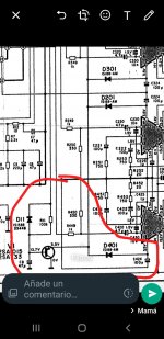
The values aren't legible on the diagram you posted but you're working with op-amps so, unless the EQ section can't withstand the higher voltage, you should be able to increase the gain of the preamp level circuit.
This is a better version of the diagram.
The values aren't legible on the diagram you posted but you're working with op-amps so, unless the EQ section can't withstand the higher voltage, you should be able to increase the gain of the preamp level circuit.
This is a better version of the diagram.
Attachments
Last edited:
Stop !!!. Wait a moment. In the @Perry Babin's schematic, there is a mute circuit affecting all 4 IC's. Did you check that?
Attachments
Regarding the ic I mentioned before (that performed really good) is Hitachi HA13158A.
If you will ever need chip for 12/14v system I would highly suggest this one. Right now it is actually powering 4 6ohm speakers in soundbar without any problem.
On the other hard there are some terible ones out there indeed.
The reason of why I want to convert the car in the boombox is because I don't necessarily want to listen to music at abnormal volumes (as I did when I was younger), it is the fact that I hate when I'm limited by power, some music has stronger bass and I don't want to listen for the clipping to turn down the volume. This defeats the enjoyment when listening to music.
The scenario:
Music that I like comes on, I turn the volume a bit up and it starts clipping, then I must turn the volume down. It kills the mood instantly.
This is what it is happening with stock stereo in my daily driver and I hate it for that. Again not abnormal volumes, some music is just bass heavy.
But I do have a confession to make...
When I was younger I was the guy with disco inside a car... well actually bass was a bit stronger than the disco.
I enjoyed the brutal bass, like somebody would be kicking you in the back of the head to the rithm. When you want to say something and you need to cough. My revs were jumping to the music when under 3000rpm, car would sometimes stall and board computer would just spit random Fs on the screen.
My hearing is damaged now, not much, but it is.
Avoid doing this please.
But I was the guy that would also upgrade the door speakers and sound deaden the doors, use HPF at 100hz... all of that so highs could keep up with the bass.
And in all this nonsense I would still set my gains with o-scope.
Bass setup was:
Ground zero gziw12 2x2ohm sub in 60L ported box (to 60hz if I remember correctly)
SinusLive SL-A1500 amplifier
Then you have guys that believe that they have 5000w chinesse amp... yeah right and that amp has 30A fuse... listening to nothing but clipping and no highs...
Something like that could work.Aint that right!
BTW this would work if the board fits physically in the BEA80: https://www.amazon.de/TDA7388-Verstärkerplatine-Kanäle-V-14-PCB/dp/B07RQ51GY3
I made a mistake by mentioning TDA7394 as it is a 2 channel IC.
I'm using DIN inputs.Are you using the speaker level inputs or the DIN inputs?
The values aren't legible on the diagram you posted but you're working with op-amps so, unless the EQ section can't withstand the higher voltage, you should be able to increase the gain of the preamp level circuit.
This is a better version of the diagram.
I was thinking of setting the gain higher, but in case of clipping I would make single 4558 / NE / TL preamp with say gain of 4 and the output of the eq.
Nice find, honestly I didn't look into it. I guess removing the transistor would be the fastest way to confirm it for sure.Stop !!!. Wait a moment. In the @Perry Babin's schematic, there is a mute circuit affecting all 4 IC's. Did you check that?


Would removing it be right way to test it?
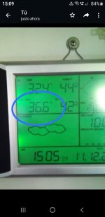
I tested it with oscope and I get this on all 3 pins:

EDIT:
Forget the picture... bad ground to o scope is the cause, it's all straight line.
Dont mind the voltages, this oscope is ****.
DMM shows:
13,7v on base
6,4v on emitter
Collector = gnd
Schematic says 3.5v for emitter... something is going on there...
One of the fautly ics could cause it I beleive?
If correct I would remove the diodes, this way I could see if transistor or one of ICs is pulling voltage to 6.5v.
Last edited:
- Home
- General Interest
- Car Audio
- Blaupunkt BEA80 / TA7270P ic