Fingers crossed that’s done trick went over the entire tracks with a C10 & X 15 loupe no cracks some of the board is bulging but has not affect the tracks where they are.
All I have not done is put new pins in.
The zener tested out of circuit that’s fine. I think it’s the old geranium type but the code on it is not very comprehensible. C52 55x I’ve found no reference to that code.
All I have not done is put new pins in.
The zener tested out of circuit that’s fine. I think it’s the old geranium type but the code on it is not very comprehensible. C52 55x I’ve found no reference to that code.
Did you build the other board as well?
Sid
No chance I prefer to spend another hour doing a proper one.
(mirror board in the bin)
The zener tested out of circuit that’s fine. I think it’s the old geranium type but the code on it is not very comprehensible. C52 55x I’ve found no reference to that code.
That zener (12v) is only a voltage reference for the TIP29C transistor and that part of the circuit doesn't affect the workings of the power stage ( R19, ZD1 and TR10 are just a power supply for the VU Meter)
Yeah I knew that after posting.
Anyhow got the output down to 9.6v from 40v large drop but still no where it should be. I'll set the trimmer exact to other see what happens.
Then I'll measure across the resistors already did couple but all seem to be at the input end where readings are not tallying up with the other module. So trimmer in a minute then have another measure. I'm convinced it's that other 100uf cap bad batch as they where cheapies don't usually skimp on price. Or that 2200pf foil cracked internally. Or it is the J50 not making proper contact. Still see in a minute.
No chance I prefer to spend another hour doing a proper one.
(mirror board in the bin)
In my warped mind I was thinking all the components except the TO3s could be flipped.
TO3s gate and drain would be reversed but then if they were rotated 180deg the pins would be the right way round but offset.
Hence my comment drill 4 new holes.
I think it would have looked cool (weird but cool) having mirror imaged left and right boards in an amp.
Totally understand your approach to having them correct though.
Sid.
I give up on this one never known anything like it.
C3 C1 R18 across to C7 R15 R17(L1) all either too high or too low. So think it’s leading to the mosfets. Plus readings jumping all over the place I’m assuming the current is swinging back and forth causing that. Definitely nothing broke on track unless it’s a hairline crack but all been checked. Everything else seems to be sitting the same.
Got sil pad coming tomorrow so I’ll clean of that crap put them on then swap round the mosfets and see what happens. But for now had enough. Don’t usually give up but none of it makes any sense to me at all. How on earth can linked components be fine then the other is way off.
I give up on this one never known anything like it.
Don’t usually give up but none of it makes any sense to me at all. How on earth can linked components be fine then the other is way off.
Just give it a rest for a few days at the end of the day is going to be something stupid like a resistor.
Just take you mind of it for a few days and try again.
Chris,
you've come too far to give up now.
Post some pictures of the solder side of the board then take a break.
You'll get there in the end.
Sid.
you've come too far to give up now.
Post some pictures of the solder side of the board then take a break.
You'll get there in the end.
Sid.
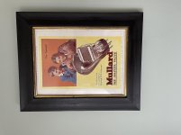
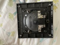
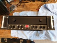
Cheers guys yeah definitely need break from it. Ha ha I’ll take a picture of underside for ya tomorrow as I’ve gotta unbolt it remove couple leads so I can flip it. Here’s a good pic I was given for free good old Millard. I re done the frame though was bit tatty.
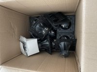
What else was gonna say is I have around 10 original Motorola piezo tweeters not the copies and two copies in there boxes think there all reclaimed but work perfectly. The sound pretty darn good considering don’t need a crossover network. Obviously PA gear but don’t need them so if someone can make use of them more than welcome to them. Just sitting in box never gonna get used by me I was gonna shuve couple on baffle board of me H&H PA speakers but then authenticity gone out the window.
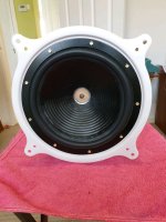
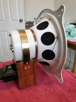
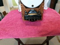
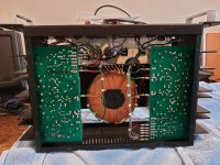
Oh here’s pics of a 1929 loudspeaker I refurbed the sound is amazing believe it or not. This one will rattle your cabinets in ya living room. Had to put foam surround on could not get hold of the original spec cloth. In sherwood cabinet I salvaged. Bit of therapy ha ha. Got another little superhert AC/DC set needs doing rare little beasts but all live chassis and no mains transformer just little output a lot people don’t like working on them but once up and running produce a nice sound. Plus can pick up stations from all over the world quite therapeutic of an evening sifting through all different stations. Ah that’s better cleaned me head up ha ha. Not relevant obviously.
I’ll post some pics of those tweeters.
What else was gonna say is I have around 10 original Motorola piezo tweeters not the copies and two copies in there boxes think there all reclaimed but work perfectly. The sound pretty darn good considering don’t need a crossover network. Obviously PA gear but don’t need them so if someone can make use of them more than welcome to them. Just sitting in box never gonna get used by me I was gonna shuve couple on baffle board of me H&H PA speakers but then authenticity gone out the window.
Oh here’s pics of a 1929 loudspeaker I refurbed the sound is amazing believe it or not. This one will rattle your cabinets in ya living room. Had to put foam surround on could not get hold of the original spec cloth. In sherwood cabinet I salvaged. Bit of therapy ha ha. Got another little superhert AC/DC set needs doing rare little beasts but all live chassis and no mains transformer just little output a lot people don’t like working on them but once up and running produce a nice sound. Plus can pick up stations from all over the world quite therapeutic of an evening sifting through all different stations. Ah that’s better cleaned me head up ha ha. Not relevant obviously.
I’ll post some pics of those tweeters.
Attachments
Well here ya go pic of underneath. Looks okay to me.
Sorry about all that buff bit of therapy from pure frustration ha.
Sorry about all that buff bit of therapy from pure frustration ha.

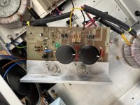
Check there are no shorts where I have indicated in yellow and check the soldering where I have indicated in red.
Probably just the camera angle but no harm in checking.
It looks much better since you cleaned it.
Sid.

Probably just the camera angle but no harm in checking.
It looks much better since you cleaned it.
Sid.
Yep will do. Yeah cleaned up okay definitely no hairline cracks in it. Had a bloody good look even slightly bent the board just to see if anything separated.
Can see that solder joint not completely covered the lead out bit of an air bubble. Well what it looks like. Still see tomorrow. Me sil pad came blimey pretty thick could put that on back of the transistors and main heatsink and the mosfets on heatsink. Nice and soft so it will definitely fill any gaps.
Cheers Sid
Bought one of these FR4 Copper Clad Laminate PCB Printed Circuit Boards 2mm thick so I can make a new one up. Slightly thicker than original. So that should do trick if all else fails plus there cheapish.
Skimmed the thread but not carefully. Is the problem transient loud crackles & pops? If so, I've looked at 6 MF100 amps with this problem: two mine and four belonging to a friend, all bought in the 90s IIRC, all ended up crackling with large, fast transients 5-10 years later - I forget exactly.
I never managed to locate the problem. It wasn't poor soldering or PCB cracks, for sure, as I resoldered a couple and checked continuity everywhere. Interestingly, similar problems did not manifest in some MF200/300models bought around the same time.
I suspect it was due to overheating somehow: In the 00s sometime, BK said they'd not had any reports of this problem, which surprised me due to there being 6/6 failures. I guess therefore it was how they were deployed rather than the design. We probably didn't have enough heatsinking. I focused on the voltage amplifier stage (MJE340?, I forget) as that was too hot, but changing the transistor didn't help.
Sorry that's not encouraging, but I thought it might be of interest.
Ken
- Home
- Amplifiers
- Solid State
- BK Electronics mosFET 100 watt modules