Hi all!
Thanks for all the humor on the forum: Jocko, Dirty Harry and all the rest!
(how's that rich kid doing?)... but now serious:
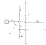
I found out that I use only very little voltage when listening in my small room in the evening. Thus I wanted to design a class A voltage folower using BJT's capable of driving 8 ohm speakers and 32 ohm headphones at 0.7 volt RMS. I have come up with this circuit.
Can anyone help me with a improvement on the topology?
Greetings,
Thijs
Thanks for all the humor on the forum: Jocko, Dirty Harry and all the rest!
(how's that rich kid doing?)... but now serious:
I found out that I use only very little voltage when listening in my small room in the evening. Thus I wanted to design a class A voltage folower using BJT's capable of driving 8 ohm speakers and 32 ohm headphones at 0.7 volt RMS. I have come up with this circuit.
Can anyone help me with a improvement on the topology?
Greetings,
Thijs
Attachments
Thanks Jocko.. looking foward to it..I'll sit tight 🙂
Hi Darkone: thanks for the schematic, since AC coupling at the ouput is OK for me the offset is no problem, but I would like to try to DC couple the buffer some how..
Hi papa Harry 😉.. us kids allways simulate before firering up.. but thanks for the warning. I just finished reading app note 227 of Nat Sem and this might give some inspiration.. I'm still aiming for a buffer with low component count and reasenable performance. Maybe you've got any ideas?
gr,
Thijs
How low is the parts count you are aiming for, and how high can the output impedance be? BJT or MOSFET?
A month or so ago......I believe "CAPSLOCK" asked about the so-called diamond buffer. I think the thread faded away. That is an option.
Jocko
A month or so ago......I believe "CAPSLOCK" asked about the so-called diamond buffer. I think the thread faded away. That is an option.
Jocko
Hi Jocko,
Thanks for your interest..
Output impedance needs to be low enough to drive speakers whitout dissipating to much be may be sub-optimal (1 ohm ?). For headphones this doesn't matter that much.
I'm trying to make a small buffer-amp (in size that is). I would like to keep dissipation low and parts count low to keep the whole thing small. I was also thinking about the Hiraga Monster topology I aim at more relaxed spec's I figured I could do with less parts somehow. I was actually also aiming at a lower supply voltage than the +/- 15 Volts as shown in my schematic..that's why I used BJT's, less dissipation, less voltage needed, etc.
I'm really currious about how such a thing would sound. Loud enough?, Bi-amped? It could turn out a nice thingy if it stays simple, cheap, maybe even tri-amping, paralelling for 4Ohm use.. battery driven.. you name it.. it could be very flexible and handy to try things out..
I hope you understand my aim a little bit, I hope it makes sense...
gr,
Thijs
Re: DarkOne
Do you think so!? hahhahaahhahahahaaaaaaa ... hhmmrmrmrpppfff hahaha (I am laughing my self to dead!!!!)
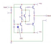
Low distortion from a BJT buffer (diamond) => highly linear current gain and a high idlecurrent. of course without feedback!
Sonny
HarryHaller said:His speakers are going to love the ~-2V DC offset. Don't try this one at home kids.....
Do you think so!? hahhahaahhahahahaaaaaaa ... hhmmrmrmrpppfff hahaha (I am laughing my self to dead!!!!)
Low distortion from a BJT buffer (diamond) => highly linear current gain and a high idlecurrent. of course without feedback!
Sonny
Hi Sonnya and Jocko,
I just read everything I could find on 'diamond buffer'. Great stuff ...nice reading!
I now realize I should use high linear devices (no 2N3055 this time .. I sometimes learn stuff here too) .. and bias heavely... but that's what I want to avoid..
I am aming at 1.6Volt peak to 8 ohm: that's 200mA. In push-pull Class A this needs at least 100mA idle..I don't wanna go higher than 150mA.. else I will need real heatsinks at so on.. I would like to keep idle dissipation under 2 watts.. maybe I'm not realistic.. hmmmm
You see: I have this picture of a nice little, no large heat sink, no complicated circuit, easy regulated power supply, above all great sounding buffer-amp in my head..and it wants to get out!
I wanna build six of them , 4 to try a low volume Bi-Amp set-up and 2 for the Grado's..
oke .. I won't anoy you any more .. back to the simulator again..
gr,
Thijs
Good for you that you skiped the first verision! I think that the highly unsymmetrical output stage would create rather much distortion if you had used it without feedback (even with feedback) . 5-10 ohms for positive half period and 1-10 kohms for the negaitve.
If you want even lower distortion use current generators instead of the 220 ohms resistors. Check my current feedback amp for inspiration. I have tested my design in real life. Works good.
http://home5.swipnet.se/~w-50719/hifi/qrv03/index.html
If you want even lower distortion use current generators instead of the 220 ohms resistors. Check my current feedback amp for inspiration. I have tested my design in real life. Works good.
http://home5.swipnet.se/~w-50719/hifi/qrv03/index.html
I think that Paranders sugestion of to change the 220 Ohms resistor for a CCS is a good one for 2 reasons:
-As Paranders says it will have lower distortion with the CCS.
-A CCS will have muche more isolation from power suply noise and the circuit will be more independent of the quality of the suply...always a good thing!
regards
Jorge
-As Paranders says it will have lower distortion with the CCS.
-A CCS will have muche more isolation from power suply noise and the circuit will be more independent of the quality of the suply...always a good thing!
regards
Jorge
A CCS will have muche more isolation from power suply noise and the circuit will be more
Thanks...good sugestion! I'll try!
greetings,
Thijs
Waaaoowwww...... peranders, just had a look at your headphone page ... overdesign probbably is the understatement of the year. This is one overspec'ed design .. I hope you build a final version soon and evalute sonically. I don't understand the topology yet but I'll have a go tomorow again... thanks for the link.
gr,
Thijs
gr,
Thijs
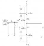
The emitter resistors are too high. A variation I use moves R6 & R7 to the bases leads of Q3 & Q4. You can adjust these to change the output current. The outputs should be at least 100 mA to keep output Z down.
Another variation puts a simple follower in series between the supply rail and the outputs, to increase PSRR.
Jocko
Another variation puts a simple follower in series between the supply rail and the outputs, to increase PSRR.
Jocko
Hi Jocko,
Your suggestion to move R6 and R7 to the bases of Q3 and Q4 work..( I used 1.5K) in fact the (simulated) distortion is lower and more focused to lower harmonics.. Voffset is higher .. hmmm
one problem: I don't understand the circuit anymore 🙁
gr,
Thijs
Your suggestion to move R6 and R7 to the bases of Q3 and Q4 work..( I used 1.5K) in fact the (simulated) distortion is lower and more focused to lower harmonics.. Voffset is higher .. hmmm
one problem: I don't understand the circuit anymore 🙁
gr,
Thijs
Moving the resistors is just another way of adjusting the current in the output, and it should remain more constant as load current goes up. It presents a lower impedance to the base of the outputs.
The values you use are too high. Around 100 ohms usually works.
Jocko
The values you use are too high. Around 100 ohms usually works.
Jocko
Thijs
The four transistor buffer you are proposing to use is fine for relatively light loads (>1kohm) but I understand you are proposing to use it with 8 to 32ohm loads. In which case, the circuit with a simple output pair will not have adequate drive capability to maintain acceptible distortion levels. I suggest you consider replacing your Q1 and Q2 with Sziklai pairs (CFP), adjusting resistor values as necessary to maintain your desired Iq.
Geoff
Hi all,
I would like to thank you all very much for your replies, since nobody seems to care about this project of mine. I don't care, I still think it's a good idea.
I've simulated alot the past vew days, all new proposed circuits were improvements on the former. i have faith this idea is going to work out just fine.
I went to the electrical shop this day and got myself the parts for three buffers, including voltage regulators, for 12 Euro's. This is gonna be a cgeap little experiment 🙂
Hi Geoff,
I don't think I understand you. Why won't it work?
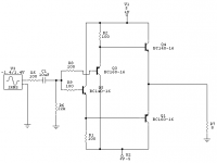
I simulated the circuit and all I can see is that it should function OK. I intend to use only 1Vrms as input maximum, and use 100mA Iq (class A) for the ouput BJT's. They will dissipate 500mW. Since they are designed for 1000mA, 60Volt, and 800mW they should not break. Ouput impedance seems to be around 0.4 Ohm and input impedance around 6KOhm. Distortion as simulated is around -75dB 2nd and 3rd, all other much lower (-110dB), bandwidth: several Mhz:
Any reason why it won't be a great little low-SPL amp or headphone amp?
Here is my final (?) version.
greetings,
Thijs
I would like to thank you all very much for your replies, since nobody seems to care about this project of mine. I don't care, I still think it's a good idea.
I've simulated alot the past vew days, all new proposed circuits were improvements on the former. i have faith this idea is going to work out just fine.
I went to the electrical shop this day and got myself the parts for three buffers, including voltage regulators, for 12 Euro's. This is gonna be a cgeap little experiment 🙂
Hi Geoff,
I don't think I understand you. Why won't it work?
I simulated the circuit and all I can see is that it should function OK. I intend to use only 1Vrms as input maximum, and use 100mA Iq (class A) for the ouput BJT's. They will dissipate 500mW. Since they are designed for 1000mA, 60Volt, and 800mW they should not break. Ouput impedance seems to be around 0.4 Ohm and input impedance around 6KOhm. Distortion as simulated is around -75dB 2nd and 3rd, all other much lower (-110dB), bandwidth: several Mhz:
Any reason why it won't be a great little low-SPL amp or headphone amp?
Here is my final (?) version.
greetings,
Thijs
Attachments
Try go looking at my homepage and download the two doc's... They do not tell you what you should do different but it will give you an idear what they where talking about ... when they mentioned current source
Sonny
Sonny
- Status
- Not open for further replies.
- Home
- Amplifiers
- Solid State
- BJT buffer design, can anyone help