Hi,
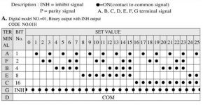
I have been playing with the idea to operate my R-2R relay based attenuator using the mechanical binary coded switch (see attached) instead of using the arduino based controller. The switch has 5 bit binary code output but only allows 26 steps out of 32 which is still enough for normal use. The switch is non-shorting which means that when you turn the knob it will always drop all bits before setting them again. And here comes the 6th "Inhibit" bit which is used to hold/update the switch state using some logic ICs. This bit is HIGH between switch positions as shown in the attached code table. My problem is that I have limited knowledge about the logic parts nomenclature and do not know where to start looking. Could someone point me to the correct logic ICs to implement such switch? It just has to update the binary output on the “Inhibit” bit falling edge which would make sure that the new state is already ON when this happens.
Regards,
Oleg
Attachments

I think a 'binary decoder' will give you some info, but you should first decide on the next step.
Suppose that you decode the switch positions into a row of 26 bits, of which one becomes active depending on the switch position.
What will you do with that? Are you looking at a 26-sections ladder switch, or some form of combinatorial attenuator like -2, -4, -8, -16, and 32dB? and various combinations? You can use the switch codes as they are if the LSB switches -2dB and the MSB -32dB for a total range of 62dB.
Jan
Last edited:
The plan is to use the encoder output as is to control the 5 bit R-2R attenuator with 2dB step as you wrote:
... or some form of combinatorial attenuator like -2, -4, -8, -16db...
Well then no decoding is required - each bit controls it's own relay. Done. ;-)
Maybe use a latch/buffer with inhibit input for smooth operation.
For instance a http://www.nxp.com/documents/data_sheet/74HC_HCT573.pdf that allows you to load the new data to the output with an 'LE' latch enable, which can be driven by your inhibit bit.
Such a latch can drive a relay too; there are many versions.
Jan
Last edited:
Exactly this sort of solution I am looking for:
I just need a bit more info on the "latch/buffer" implementation or at least the ICs involved.
Well then no decoding is required - each bit controls it's own relay. Done. ;-)
Maybe use a latch/buffer with inhibit input for smooth operation.
I just need a bit more info on the "latch/buffer" implementation or at least the ICs involved.
The problem in using the encoder as-is is that it will always drop to full attenuation between steps which I would like to avoid.
The problem in using the encoder as-is is that it will always drop to full attenuation between steps which I would like to avoid.
I don't think so. The latch enable will be less than a usec. In that period, relays will not drop out. So the new relay setting will almost certainly be inaudible.
Check out the 74HC(T)573 and its brothers.
If you want to precisely define the switching point use a D-type flipflop like a 7474.
Jan
Thanks a lot Jan! This is exactly the info I've been looking for! Now I have a good starting point.
Check out the 74HC(T)573 and its brothers.
If you want to precisely define the switching point use a D-type flipflop like a 7474.
Jan
Thanks Mona!
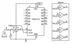
I've just been googling for the inverter for latch enable pin when you posted🙂 Your diagram is what I'm going to try. I probably need a hardware debounce (RC) on all encoder outputs for smooth operation.
I've just been googling for the inverter for latch enable pin when you posted🙂 Your diagram is what I'm going to try. I probably need a hardware debounce (RC) on all encoder outputs for smooth operation.
Last edited:
Perhaps not nesserairy.The state of the swithes is stored on the edge of the puls, what happens in between doesn't matter.
Mona
Mona
If I may ask : why the move away from arduino ? This switch is 58$ alone. That's a lot of arduino boards.
It saves a lot of real estate inside of chassis. It also removes arduino with its 12 or so MHz operation as well as 400+ kHz I2C communication line which is not a coupled differential pair and thus can be noisy especially if it's higher frequency variant is used. I actually do not know how much this is a problem in terms of the radiated noise but I guess the conducted noise is there and thus the entire controller part needs separate power supply. This quickly becomes problematic in tight spaces, e.g. inside of headphone amp. In contrast the mechanical rotary switch with a single IC and a bunch of relays can be used on the same power lines as the analog circuitry without the high frequency noise issues.
By the way, speaking of the cost of arduino based solution, a good quality rotary encoder costs at least a half of the switch price. I already have an arduino based solution which I am happy with but it required big chassis to host all the bits.
In fact, you do not even need relays and logic: you can wire your audio in to the common, and connect resistors in a 1-2-4-8-16 sequence to the bits, to feed a transimpedance amplifier, or even just a simple resistor, in which case you'll need to alter slightly the values to compensate for the non-linearity of the resistive divider.
An R2R network won't be usable here, because the inactive bits are left floating, not grounded.
You won't be able to use the inhibit signal, unless you use some trick with the DC level of the input, but I don't think it is a big issue.
An R2R network won't be usable here, because the inactive bits are left floating, not grounded.
You won't be able to use the inhibit signal, unless you use some trick with the DC level of the input, but I don't think it is a big issue.
Thanks for the hints Elvee and Osvaldo!
There is a little problem with using the encoder directly as the attenuator - it has only one deck but for stereo there should be at least two.
The idea to implement simple counter is interesting. I have no idea where to start with it but I'll dig into it🙂
Regards,
Oleg
There is a little problem with using the encoder directly as the attenuator - it has only one deck but for stereo there should be at least two.
The idea to implement simple counter is interesting. I have no idea where to start with it but I'll dig into it🙂
Regards,
Oleg
It is easy. Genearte a low frequency clock signal, say 1Hz (7555 or CD4047). Apply this signal to 2 buttons, one called "up", or +, the other, down, - or any other label you want. The outputs or both, wired to a 40192, 40193, 74hc192 or 74hc193, that are decade/binary 4 stages ripple counters, with increasing and decreasing inputs, and carry and borrow outputs, to link many of them.
The counted outputs, go to a 4028 which converts BCD or binary to decoded outputs. From any of the outputs, you go to low power mosfets, as BS107, 2n7000, etc. Then, with them you manage the coil of a relay. A master reset applied to the counters chain ensures clearing all of them at the power up, and you can define the default input of the system with it.
I used a circuit like this to replace the rotary swith of an old BC rig, a Mc Kinley one. Works pretty fine.
From decoded output, a led or a 7 segment display can illuminate, indicating input selected, or the number of input selected.
If you want to try, give me a couple of days and prepare the schematic for you.
- Status
- Not open for further replies.
- Home
- Design & Build
- Parts
- Binary code rotary switch