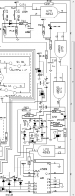
This circuit is probably a good start: it is in fact the range selection for an instrument I designed, but bits are agnostic, and you can use them i!n whatever way you want.The idea to implement simple counter is interesting. I have no idea where to start with it but I'll dig into it🙂
The schematic section is not very legible, sorry about that, but since it's not that complicated, you will probably be able to figure out the circuit.
Here, it is designed for 4 bits, of which 3 are used, but you can cascade another counter for more bits by just following the cascading instructions included in the 4029 datasheet.
The circuit remains fully static when no modification is entered, and it even offers an auto-repeat function if you keep one of the buttons depressed
Edit:
Obviously, neither the LED indications nor the diode outputs decoding apply in your case
Attachments
Last edited:
Thanks for the offer, Osvaldo! I am definitely interested to try but I would prefer a rotary encoder as an input. I have a couple of Bourns EM14 series optical encoders with quadrature output lying around. Is there a way to use such to drive the counters? I just don't like using buttons for volume control duties.
Regards,
Oleg
Regards,
Oleg
Thanks for the schematic, Elvee! I think I'll manage to fully understand it. I'll also look for a simple circuit to detect CCW and CW encoder rotations to replace the buttons.
If you take a CD4029 up/down counter with the rotary encoder outputs on the up/down input and the clock, the counter goes up or down depending on the direction you turn.
Mona
Mona
Thanks Mona! This IC looks interesting for the encoder control. I'll have to educate myself a bit on how to properly use digital ICs but it all seems to be not too difficult.
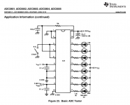
I think I found a better solution for my needs. Attached is the basic ADC circuit which can directly drive R-2R attenuator through its parallel outputs. Just hook up the wiper of a linear pot to Vin pin while connecting the pot between supply and GND and you are good to go. The advantages are circuit simplicity, no need for expensive switch, and volume knob would actually indicate the volume setting which is not so trivial to achieve with rotary encoder. Internal clock can be made slow enough not to contaminate the system with EMI. I would need to provide a reset pulse after power on instead of the switch for automatic ADC start. I guess a simple flip-flop fed by RC delay networks on its inputs with slightly different delay times would provide a reset pulse. Or maybe I can just use a timer IC like 555 for this.
Regards,
Oleg
Regards,
Oleg
Attachments
- Status
- Not open for further replies.