Gareth,
Nice circuit, elegant.
Only problem I see is quiescent control in the outputs; as I see it, Iq relies on Vbes of Q3/Q1 and Q6/Q2, which are temperature dependent but may still track pretty well.
You could set Iq in stone with an 'emitter' degen resistor on Q1 and Q2, but you may need to add a small resistor to the emitters of Q3 and Q6 to set the bias.
I have not done the temp param plot, so it's possible it could be OK, but it is a potential pressure point and only a breadboard would show any instability.
Keeping up the pressure......!
Hugh
Member
Joined 2009
Paid Member
I think a simulation is in order.
I know your will have some fun .
I'm must go to sleep now.
Thanks everyone for the encouragement ...Bonsai, Carlos, Hugh etc. -
and Lumba, I haven't forgotten about JFET's

Okay Bigun, that's a negative.
The current mirror actually reverses the compensation polarity so while it compensates for the PNP input transistor, it makes it worse for the NPN. We would have to drive both of the input Q's with tricked CCS's. May be worth it, maybe not.
- keantoken
The current mirror actually reverses the compensation polarity so while it compensates for the PNP input transistor, it makes it worse for the NPN. We would have to drive both of the input Q's with tricked CCS's. May be worth it, maybe not.
- keantoken
Hey Bigun,
The v3 looks very interesting. Novel circuitry! Although I really like the original JLH tubelike concertina topology🙂.
Quite a leap forward from the JLH follower(simple non-ziklai version of your v1) I showed in passlabs/hififorum some year ago. But actually I found it in a book published by Wireless World in the early seventies.
Must do a side by side comparision.
Last edited:
Member
Joined 2009
Paid Member
Any concerns over the particular devices I have chosen - 2N5401/2N5551 and BD139/BD140 ?
these are good devices, largely enough for a low power amp...
if current gain is an issue, you can replace the 5401/5551 by
bc546b/556b wich have higher gain while being very cheap...
Last edited:
Member
Joined 2009
Paid Member
yes, no voltage gain. Voltage gain is not always needed. My source (CD, FM tuner etc.) puts out 2V or more. Put 2V into a speaker and depending on your situation you may already have more than enough volume.
I may want some voltage gain. I plan to introduce a front-end to the design, but later. My approach is to design this in pieces with no global feedback. If later I want global nfb, it can be accommodated.
I may want some voltage gain. I plan to introduce a front-end to the design, but later. My approach is to design this in pieces with no global feedback. If later I want global nfb, it can be accommodated.
Hi Bigun;
may be now you can dig this one. 😉
http://wavebourn.com/forum/download.php?id=127&f=7
(My concept, drawn by Peter Ken. )
may be now you can dig this one. 😉
http://wavebourn.com/forum/download.php?id=127&f=7
(My concept, drawn by Peter Ken. )
Last edited:
Member
Joined 2009
Paid Member
Yes, I'm impressed you remember my interest.
I saw this some months ago, I think I tried to simulate it - if I remember it was something about the possibility of soft clipping that first attracted me to it ? Anyhow, I didn't understand it and moved on.
Now it looks not so strange. It looks like a very nice Sziklai Follower with an elegant method of ensuring a Class A bias point. It uses fewer transitors than my double-JLH - although no fewer PN junctions 😉
This is a good candidate for Option 4: Did you build it - how does it sound ?
Nuclon was simulated, THD seems a little bit high...i have changed something
but the distortion is still high.
It is just an output, needs a lot of swing to make this work.
Seems nice, but needs some professional touch from Wavebourne or from you Bigun.
regards,
Carlos
but the distortion is still high.
It is just an output, needs a lot of swing to make this work.
Seems nice, but needs some professional touch from Wavebourne or from you Bigun.
regards,
Carlos
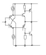
You may see it as a Sziklai follower if don't pay attention to diodes in feedback, or you may see it as a complementary opamp with VAS stages loaded one on another. LTP stages are implemented by transistors (left) and diodes (right - D2, D3). Output transistors with diodes in bases (D1, D6) work as current mirrors.
Tails of LTPs intentionally use resistors so their maximal current will depend no a voltage swing. And diodes (D4, D5) with resistors in series turn the amp into AB class, without such diodes and resistors it would be class A follower.
Yes, the main advantage is, smooth clipping and self-protection against too low load impedance.
However, D2 and D3 theoretically may be replaced by transistors for classical LTP implementation, but Vbe breakdown voltages of modern transistors are below 6V so when "self-protection" starts working they would be blown.
Also, if to replace D1 and D6 by transistors you will see classical current mirrors.
Yes, I built it many times in 1980'th, to replace dead ICs in car radios. Owners were happy because they could not damage anymore their precious Japanese gear shorting out outputs. 😀
And it sounded much better than Japanese ICs.
Before that, I built such an output stage (bridged) for a guitar amp with blown output transformer. Actually, I made my first Hybrid amp back in 1982, but "Hybrid" word was not familiar then yet. It sounded very tubey. The amp was BEAG guitar head made in Hungary. The owner was happy: the sound was better, he did not need anymore to buy and swap EL34 tubes, and the head could be used with bass guitar as well (of course, no output tranny anymore!)
Last edited:
Seems nice, but needs some professional touch from Wavebourne or from you Bigun.
You are right Karlos. Probably resistors in tails still need to be adjusted depending on betas of output transistors, since as drawn ratios of current mirrors are a bit too high to forget about adjustments.
Member
Joined 2009
Paid Member
It is just an output, needs a lot of swing to make this work. Seems nice, but needs some professional touch from Wavebourne or from you Bigun.
Carlos, you flatter me, but I haven't made 'professional' grade yet. I realized that this month is the 1 year anniversary of my start in this new audio hobby. I joined DIY Audio 17 January 2009 with no memory of ever completing a circuit that worked.
Lots of swing is OK, I'm building a Follower first. We can pass the problem of swing to the front end and deal with that later.
You may see it as a Sziklai follower if don't pay attention to diodes in feedback, or you may see it as ...
I haven't the ability to see all these things yet, but I have noticed how many circuits can be seen in different ways - part of the reason why I feel all amplifier topologies are only separated by '6 degrees of freedom'.
Yes, the main advantage is, smooth clipping and self-protection against too low load impedance.
I need to look at this a bit more, they are both desirable. On the other hand, for my first foray into Class A I might have to tread more familiar ground first. And if you saw the materials I have on hand (first post) it doesn't look like it's worth optimizing too many things - it's going to have some layout challenges (hum for example).
In the 1980's I was still in school....
I need to look at this a bit more, they are both desirable. On the other hand, for my first foray into Class A I might have to tread more familiar ground first. And if you saw the materials I have on hand (first post) it doesn't look like it's worth optimizing too many things - it's going to have some layout challenges (hum for example).
I would personally replace Q4/Q5 current source by a plain linear resistor, and added between base of Q2 and minus a PN junction with resistor in series, and one resistor in it's emitter. Such a way I would turn Q2 into a current mirror, and it's current would depend on a voltage swing.
Gareth,
if I used a current mirror here I would apply it symmetrically. The question is what does it accomplish for these heavily class A biased stages?
if I used a current mirror here I would apply it symmetrically. The question is what does it accomplish for these heavily class A biased stages?
Member
Joined 2009
Paid Member
To be honest, I'm not convinced that the double-JLH provides enough benefit over the earlier options. Options 1 & 2 appears to be quite satisfactory - need I chase for more performance than these offer ?
Symmetrical = reduces H2. Generally a good thing, unless it also fails to pull down H3, which is often the case.
Symmetrical = reduces H2. Generally a good thing, unless it also fails to pull down H3, which is often the case.
Member
Joined 2009
Paid Member
Gareth,
if I used a current mirror here I would apply it symmetrically. The question is what does it accomplish for these heavily class A biased stages?
I've used the current mirror as a means to 'communicated' the current from the CCS that is used on one Output over to the other output so that I can use one CCS instead of two. Now I only have to set the current at one place and employ temperature compensation in one CCS. It's convenience 😎
I've at least turned on the electric drill and made a cut out in the front of the first amp for the panel meter.
Attachments
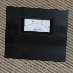
Meter is nice, if analogic one.
take care, do not make my mistake.
I have made a single sensitivity, my meter almost does not move with my 100 watts scale..only small movement.
Use a switch to have two ranges, one to 10 watts and other for 100 watts, well, make it adapted to your maximum power level in two ranges.
The volumes we use, the power we use, is less than 1 watt...meter almost does not move.
I am preparing a simple one, using Leds and resistances..we see how they work in real life.
regards,
Carlos
Attachments
Last edited:
It seems to me like needle movement should logarithmic, since power vs. perceived volume is not a linear function. Analog Devices has some logarithmic IC's.
Or, you could capacitively couple the 10W meter to a 100W meter's input so that it wouldn't max out if the power went over 10 watts. So the 10W needle would sort of act like a magnifier for the 100W needle, and would work at any volume.
- keantoken
Or, you could capacitively couple the 10W meter to a 100W meter's input so that it wouldn't max out if the power went over 10 watts. So the 10W needle would sort of act like a magnifier for the 100W needle, and would work at any volume.
- keantoken
- Status
- Not open for further replies.
- Home
- Amplifiers
- Solid State
- Bigun's Botch Up amplifier