Member
Joined 2009
Paid Member
Ah, if I could but dream of 100W... I don't expect to be able to get even 10W in Class A. But I don't complain, many others found their enjoyment at low powers. This time, I will build 4 amplifiers in these tiny boxes, just for fun and only with low power, with a voltage swing limited at most to +/- 10V when the wind is blowing in the right direction and you don't measure it too closely. More like +/- 8V. The trafo takes up almost the whole box, I'm not sure it will be an amplifier I'm making, instead it might be a 120Hz sound generator !
I was thinking of just wiring the meter to monitor the total return current to the psu. In essence it will show total current flow from both channels. The idea was to give me some means to keep an eye on the current whilst the thing heats up. The music will only be visible as wiggles in the needle.
I hadn't thought of using it to measure output power - I guess you measure the current flow to the speaker. How to do logarithmic -perhaps using a diode junction ????
Maybe I can switch it between power output monitor and total amplifier current monitor ?
I like those LEDs Carlos - perhaps they can be logarithmic like the power indicators in the laboratory of the KRELL alien race (did you see the movie that inspired the hi-fi ?)
If you look up datasheets for matched transistor pairs you should find some logarithmic amp schematics. For a simple meter maybe a diode-based on would work (would have to do with opamp measuring voltage vs. current of a diode, or vice versa. Maybe an opemp isn't even necessary?)
- keantoken
- keantoken
Member
Joined 2009
Paid Member
Hey gareth,
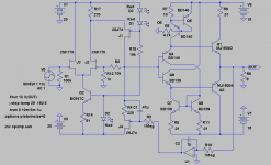
Have taken the liberty to add my driver to your "JLH/Diamante". Dumped the, in my eyes, unnecesarry Ziklai configuration.
Seems to work fine.
My gosh, that is taking liberties with a gentleman's design 😉
Regarding schematic in post #19.
This is cool. You got real JLH with Q3 doing the current steering
and top end half diamond buffering. But you flip the lower leg of
steered drive current off the bottom rail. And use complimentary
transistors.
If that was all you had achieved, I wouldn't be excited. But
you have found a way to simultaneously create a lower leg
half diamond buffer, and shunt away excess drive currents
that otherwise plague "normal" JLH in the quiescent state!
I think a small resistor or two between output emitters might
be in order to set a known quiescent??? But you would need
to open the diamond enough to accomodate an extra diode
drop. Perhaps a 0.3V Schottky in series with the emitter of
Q6 would let you add 0.33R between the bottom Sziklai pair
and the load?
-----------------------
On the other hand, I'm none too sure how the end result is
different from a simple diamond buffer with two CCS? Viewed
as-if both input comparators shunt away excess drive current.
Another valid way to look at the typical diamond.
-----------------------
Rev's #42 is interesting. Doesn't get rid of emitter voltage non-
linearites, but does assure they track both equal and opposite.
This one too needs some quiescent control? Perhaps I worry
too much when I see power transistors operating without a
well defined current limit.
Last edited:
Yeah kenpeter,
So right, this one will not be stable, must be reworked. After all it is just a diamond-buffer and they need quiescent control. But that must be valid to Biguns #19 too, I guess. The two are the same except for the Sziklais.
So right, this one will not be stable, must be reworked. After all it is just a diamond-buffer and they need quiescent control. But that must be valid to Biguns #19 too, I guess. The two are the same except for the Sziklais.
Member
Joined 2009
Paid Member
It seem only appropriate that I cut the heatsink up in the cold of a Canadian winter 😛
Yes, I made sure it was firmly clamped, used a SHARP blade, lubricated it with copious WD40, ear and eye protection, thick gloves etc.
It was easier than cutting particle board.
Yes, I made sure it was firmly clamped, used a SHARP blade, lubricated it with copious WD40, ear and eye protection, thick gloves etc.
It was easier than cutting particle board.
Attachments

Bigun, look to mythology - great swords were often forged in such conditions. To counterbalance, you need to pull the next part from the fires of hell. 🙂
- keantoken
- keantoken
Member
Joined 2009
Paid Member
The Influence of Zeus....
Well, progress is slow, but then that's why it's a hobby...
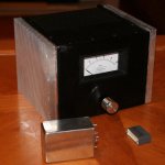
Here's a prototype chasis of the first Botch Up. There are 4 of them like this. I've obtained some nice pots from an old Yamaha Receiver, along with some nice old high performance japanese transistors. There were 4 pots, treble, bass, volume and loudness. Each black Botch Up box gets a pot.
You can see it's pretty small, heatsinks will struggle with Class A ambitions here. BUT it's a good proving ground, an R&D project to learn and play.
Unfortunately my junk box is not very deep, I've had to resort to placing an order with Digikey for capacitors at least.
In the photo you will see a couple of other things. A nice 1uf film capacitor - a pack of 20 kindly donated to my junk box by a friend. And also donated at the same time a pair of Hammond transformers.
The Voltage Amplifer will be a transformer !!!!
I have decided to stick with the Diamond output toplogy. It looks to be a very clean and desirable topology. I don't want to spoil it with an active gain stage. So I figured I should try and use a transformer for low noise low distortion gain. Yes, transformers aren't perfect, saturation at low frequencies and other nasties at high frequencies. But modern high quality audio transformers are remarkably clean over the audio range. So inspired by Susan Parker and her Zeus amplifier I hope to achieve voltage gain with the transformer and current gain with the Diamond (you see Keantoken - mythology is in here !). We'll see, it's not the ideal trafo for the job.
This will also be a ZERO (global) FEEDBACK design.
Well, progress is slow, but then that's why it's a hobby...
Here's a prototype chasis of the first Botch Up. There are 4 of them like this. I've obtained some nice pots from an old Yamaha Receiver, along with some nice old high performance japanese transistors. There were 4 pots, treble, bass, volume and loudness. Each black Botch Up box gets a pot.
You can see it's pretty small, heatsinks will struggle with Class A ambitions here. BUT it's a good proving ground, an R&D project to learn and play.
Unfortunately my junk box is not very deep, I've had to resort to placing an order with Digikey for capacitors at least.
In the photo you will see a couple of other things. A nice 1uf film capacitor - a pack of 20 kindly donated to my junk box by a friend. And also donated at the same time a pair of Hammond transformers.
The Voltage Amplifer will be a transformer !!!!
I have decided to stick with the Diamond output toplogy. It looks to be a very clean and desirable topology. I don't want to spoil it with an active gain stage. So I figured I should try and use a transformer for low noise low distortion gain. Yes, transformers aren't perfect, saturation at low frequencies and other nasties at high frequencies. But modern high quality audio transformers are remarkably clean over the audio range. So inspired by Susan Parker and her Zeus amplifier I hope to achieve voltage gain with the transformer and current gain with the Diamond (you see Keantoken - mythology is in here !). We'll see, it's not the ideal trafo for the job.
This will also be a ZERO (global) FEEDBACK design.
Attachments
Well, progress is slow, but then that's why it's a hobby...
Here's a prototype chasis of the first Botch Up. There are 4 of them like this. I've obtained some nice pots from an old Yamaha Receiver, along with some nice old high performance japanese transistors. There were 4 pots, treble, bass, volume and loudness. Each black Botch Up box gets a pot.
You can see it's pretty small, heatsinks will struggle with Class A ambitions here. BUT it's a good proving ground, an R&D project to learn and play.
Unfortunately my junk box is not very deep, I've had to resort to placing an order with Digikey for capacitors at least.
In the photo you will see a couple of other things. A nice 1uf film capacitor - a pack of 20 kindly donated to my junk box by a friend. And also donated at the same time a pair of Hammond transformers.
The Voltage Amplifer will be a transformer !!!!
I have decided to stick with the Diamond output toplogy. It looks to be a very clean and desirable topology. I don't want to spoil it with an active gain stage. So I figured I should try and use a transformer for low noise low distortion gain. Yes, transformers aren't perfect, saturation at low frequencies and other nasties at high frequencies. But modern high quality audio transformers are remarkably clean over the audio range. So inspired by Susan Parker and her Zeus amplifier I hope to achieve voltage gain with the transformer and current gain with the Diamond (you see Keantoken - mythology is in here !). We'll see, it's not the ideal trafo for the job.
This will also be a ZERO (global) FEEDBACK design.
wow, it looks nice.
Member
Joined 2009
Paid Member
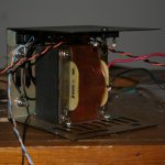
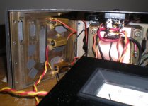
With the unbelievably tight space in this chasis I decided to add a copper belly strap to the trafo in order to reduce stray magnetic fields. It acts as a shorted-turn for leakage flux.
I soldered an in-line fuse into the mains AC - hopefully I won't be needing to regularly replace this fuse.
Installed two rectifier diodes recovered from the Acopian PSU into the chasis. These are wired in parallel with one reversed. They form a 'protected earth', isolating the amplifier ground from the chasis which is connected to safety earth.
Input phono jacks installed and two pairs of speaker connectors alongside.
Powered up the Trafo - no immediate signs of trouble, but of course there's no load at this point.
Attachments
Member
Joined 2009
Paid Member
Input select and power toggle switches added to all the boxes now.
I've also planned out the 4 different amplifiers, not sure which one will be built first though...
it's slow work, just not enough time these days.
I've also planned out the 4 different amplifiers, not sure which one will be built first though...
it's slow work, just not enough time these days.
Last edited:
Member
Joined 2009
Paid Member
This project is starting to get on my wick. There is so little space in the chasis that several compromises are needed.
It's fine in theory to use junk box parts, but there's a reason it's called a 'junk' box.
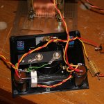
Well, managed to find the one and only spot I can fit in a bridge rectifier, added snubbers and bolted it in place. Glued a pair of filter caps to the front panel - only space available. Wired them up in a CRC configuration and included the panel meter.
Tested it with an 80R dummy load - so far so good and not as much voltage droop from the trafo as I had expected. Perhaps that explains why the darn trafo is the 'elephant in the kitchen' using up all the chasis space.
I'm looking forward to driving my car over this amp a few times when it finally proves to me that it ain't gonna work
It's fine in theory to use junk box parts, but there's a reason it's called a 'junk' box.
Well, managed to find the one and only spot I can fit in a bridge rectifier, added snubbers and bolted it in place. Glued a pair of filter caps to the front panel - only space available. Wired them up in a CRC configuration and included the panel meter.
Tested it with an 80R dummy load - so far so good and not as much voltage droop from the trafo as I had expected. Perhaps that explains why the darn trafo is the 'elephant in the kitchen' using up all the chasis space.
I'm looking forward to driving my car over this amp a few times when it finally proves to me that it ain't gonna work
Attachments
Beautiful -- a nice lamenate lump for the bzzzzt
Nice ---- even though you think this is a "junk box" project -- the things we can learn from it are still valid -- its fun also
Nice ---- even though you think this is a "junk box" project -- the things we can learn from it are still valid -- its fun also
Member
Joined 2009
Paid Member
Well I thought about using a virtual earth - never made an amplifier this way before. This would give me dual supply rails from my single secondary transformer to play with.
The design is the classic capacitor divider across the dc rails, the mid point defining ac 'ground'. A pair of bjt's in emitter follower configuration fix the dc point - they are biassed off the rails by a string of R-diode-diode-R, i.e. using two diodes to establish some bias current.
There's not enough space to put something with the power amp boards, the virtual earth will need to be constructed on an ancillary board and glued on the front panel next to the psu filter capacitors.
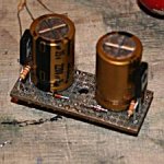
First attempt on some cheapo prototype board was a failure - the tracks lift off and the board is too flexible. Second attempt on good quality proto board was much better. Space in the botch up chasis is very tight so the board size was limited to more or less the footprint of two Nichicon MUSE audio capacitors.
First attempt blew up. Forgot the emitter degeneration resistors. Always nice to be reminded of stupid things with a little experiment like this. Rebuilt with emitter degeneration and bingo - works nice.
However, it's messy, everything very tight for space, it's hard to assemble, probably impossible to repair and generally gives me a feeling that I'm pushing my luck. All in all, it's bit 'too' DIY. I just can't live with this quality of workmanship even for a BotchUp project. I'll just be waiting for it to break. So despite the effort invested, I feel compelled to abandon the Virtual Earth approach and stick with the simpler single rail option. I will come back to virtual earth for a future project perhaps.
Here's a photo of the one that I got working...
the hole in the middle takes a bolt and spade connectors to form a Star Ground.
The design is the classic capacitor divider across the dc rails, the mid point defining ac 'ground'. A pair of bjt's in emitter follower configuration fix the dc point - they are biassed off the rails by a string of R-diode-diode-R, i.e. using two diodes to establish some bias current.
There's not enough space to put something with the power amp boards, the virtual earth will need to be constructed on an ancillary board and glued on the front panel next to the psu filter capacitors.
First attempt on some cheapo prototype board was a failure - the tracks lift off and the board is too flexible. Second attempt on good quality proto board was much better. Space in the botch up chasis is very tight so the board size was limited to more or less the footprint of two Nichicon MUSE audio capacitors.
First attempt blew up. Forgot the emitter degeneration resistors. Always nice to be reminded of stupid things with a little experiment like this. Rebuilt with emitter degeneration and bingo - works nice.
However, it's messy, everything very tight for space, it's hard to assemble, probably impossible to repair and generally gives me a feeling that I'm pushing my luck. All in all, it's bit 'too' DIY. I just can't live with this quality of workmanship even for a BotchUp project. I'll just be waiting for it to break. So despite the effort invested, I feel compelled to abandon the Virtual Earth approach and stick with the simpler single rail option. I will come back to virtual earth for a future project perhaps.
Here's a photo of the one that I got working...
the hole in the middle takes a bolt and spade connectors to form a Star Ground.
Attachments
Last edited:
Member
Joined 2009
Paid Member
do I smell BBQ ?
Well I have finished my simulations and designed a pcb layout and was about to start when I thought, hmmmm, I really should test out those heatsinks, they don't look too big.
I bolted some power resistors to the inside of the box and fired it up !
It got warm. It got warmer. It got even warmer. Then it got hot. Then it got hotter. Then it got even hotter. I could not keep my hands on the heatsink for the 5 second 'rule'. I reduced the current from 3/4 amp down to 1/2 amp and repeated. But it simply took a little longer before it was ready for the steak to be thrown on it.
So it ain't gonna work at the kind of bias currents that make Class A as good as it can be. I'm not willing to play with Class at small currents, I leave that for the headphone guys.
It seems that BotchUp will have to be converted to Class AB from thermal considerations, although output power is still limited by the low voltage trafo's. The alternative is to rip out those nice beefy trafo's and start over with some BFH (big heatsink) and do it right but then I may as well invest in some more power trafo's.
So it seems Botch Up has been botched up. I'm not at all surprised 😀
Attachments
- Status
- Not open for further replies.
- Home
- Amplifiers
- Solid State
- Bigun's Botch Up amplifier