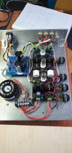
This is the one, and it's perfect for this project. Just add a Transformer shield and you'll not hear a peep out of it.
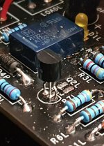
I have fitted 2x Matched 2SK170V that have arrived courtesy of our fellow member Milan!
The phonostage works with them.
Sonically, there is certainly a difference I am hearing.
Its early impressions but I am giving them a good listen. I'll let them run in a bit.
The phonostage works with them.
Sonically, there is certainly a difference I am hearing.
Its early impressions but I am giving them a good listen. I'll let them run in a bit.
Yes it is the source resistor. 0.284V is perfect giving a valve current of 6mA.
So Id @6mA is a desired value , what Idss we need to aim for then?
What is the load resistance and top voltage
I have fitted 2x Matched 2SK170V that have arrived courtesy of our fellow member Milan!
The phonostage works with them.
Sonically, there is certainly a difference I am hearing.
Its early impressions but I am giving them a good listen. I'll let them run in a bit.
can you measure around transistors , voltage on D G and S , drain voltage on the top of load resistor , value of load resistance and what resistance used on source?
If you tell me where to stick the prongs, I'll stick them there and let you know the result.can you measure around transistors , voltage on D G and S , drain voltage on the top of load resistor , value of load resistance and what resistance used on source?
If you tell me where to stick the prongs, I'll stick them there and let you know the result.
First we need to find ground , if you put - on either side of R7L or R7R and + on middle leg of transistor , whichever gives 0V is your ground .
Next keep - on the ground of R7L or R7R and + to other leg on the left of your photo - this would be drain voltage ,
next measurement - stays on ground + to leg on the right - this is source voltage ,
no need to measure middle leg as it's 0V
two more measurements from ground to either side of R6L
Drain voltage is 2.71v
Source voltage is 0.219v
Either side of R6 is 108v and 127.7v
Seems like drain sits too low , I'm at work today so having just a quick look at it , you need higher DS voltage to be in linear part of characteristic , not sure how much play is there with load - you might need to ask Alan , I'd also recalculate gain and have a look at input capacitance.
Seems like drain sits too low , I'm at work today so having just a quick look at it , you need higher DS voltage to be in linear part of characteristic , not sure how much play is there with load - you might need to ask Alan , I'd also recalculate gain and have a look at input capacitance.
I don't think there is much, if any flexibility to be honest. We were talking about this a few days ago.
You could bias it bit higher but it would reduce Id and you're already lower than 6mA , probably not a good choice I'm afraid
You could bias it bit higher but it would reduce Id and you're already lower than 6mA , probably not a good choice I'm afraid
Well after giving the 2SK170v a listen, i was concerned the sound was a littled veiled than when compared to BF861C. I added a 270R resistor to the 47R in R7 under the advice of Alan.
I still like the sound but the incisiveness of the BF861C is missing still, so it appears that even though the 2SK170V will 'work' it isnt suited to the circuit, which is a shame.
I jave some 2SJ74V, is it worth trying them?
If you fancy bit more soldering , try something like 68R in place of 47R , post some measurements if you can , what's Idss of your 2SK170 - must be above 10mA?
I'm ready to connect the board to transformer, but can't understand the markings. On my transformer it reads:
Pri: 230V blue-blue (2 blue wires)
"0" green-yellow (1 wire)
Sec I: 165V red-red
Sec II: 9,5-0-9,5V black-orange-black
From mains I should just connect phase/line to one blue and neutral to other blue wire? Or both blue ones to phase/line and green-yellow wire to neutral? Latter is what I did, but didn't get any voltage on secondaries.
Yellow green is usually earth , primary should be on blue wires - check resistance between all wires to make sure is correct
There is resistance (83ohms) between blue wires.Yellow green is usually earth , primary should be on blue wires - check resistance between all wires to make sure is correct
Check resistance between yellow/green and blue ones - yellow/green to blue and yellow/green to the other blue , just to be certain
Well after giving the 2SK170v a listen, i was concerned the sound was a littled veiled than when compared to BF861C. I added a 270R resistor to the 47R in R7 under the advice of Alan.
I still like the sound but the incisiveness of the BF861C is missing still, so it appears that even though the 2SK170V will 'work' it isnt suited to the circuit, which is a shame.
I jave some 2SJ74V, is it worth trying them?
To be honest with you I'd stick with transistor circuit was designed around unless there is something really wrong , sometimes we can miss how some little changes affect whole circuit , another option is to simulate it in Spice for example , saves soldering and de-soldering .
'
- Home
- Source & Line
- Analogue Source
- Bigbottle Phonostage Builders thread


